Cirkit Designer Logo
Cirkit Designer
Your all-in-one circuit design IDE
Home / 
Component Documentation

How to Use MAIN ISOLATOR (3P): Examples, Pinouts, and Specs

Image of MAIN ISOLATOR (3P)
Cirkit Designer LogoDesign with MAIN ISOLATOR (3P) in Cirkit Designer

Introduction

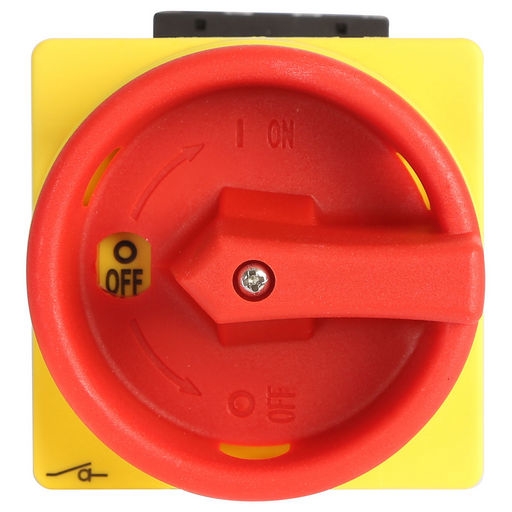
A Main Isolator (3P), also known as a triple-pole isolator, is a critical safety device in electrical systems. It is designed to disconnect all three live conductors in a three-phase power supply simultaneously, ensuring complete isolation of electrical equipment from the main power source for maintenance or emergency purposes. This component is commonly used in industrial settings, commercial buildings, and high-power electrical installations.

Explore Projects Built with MAIN ISOLATOR (3P)

Use Cirkit Designer to design, explore, and prototype these projects online. Some projects support real-time simulation. Click "Open Project" to start designing instantly!
Industrial Power Distribution and Safety Control System
Image of Control Diagram: A project utilizing MAIN ISOLATOR (3P) in a practical application
This circuit is designed for power distribution and safety control in an industrial setting. It features a main isolator and circuit breaker for power management, multiple PSUs for 5V, 12V, and 24V outputs, and a safety relay system that interfaces with E-stop buttons and a start switch to control a main contactor, ensuring safe operation and emergency power cut-off capabilities.
Cirkit Designer LogoOpen Project in Cirkit Designer
ESP32-Based Wi-Fi Controlled 24V Input/Output Interface Module
Image of ESP32 4 på rad: A project utilizing MAIN ISOLATOR (3P) in a practical application
This circuit uses an ESP32 microcontroller to interface with a 3.3V PNP to 24V NPN photoelectric isolation module, which in turn connects to a 40-pin connector for general-purpose input and output. The 24V power supply provides the necessary voltage for the isolation module and the 40-pin connector, enabling the ESP32 to control and monitor high-voltage signals safely.
Cirkit Designer LogoOpen Project in Cirkit Designer
PID Temperature Control System with Thermocouple and SSR
Image of IR: A project utilizing MAIN ISOLATOR (3P) in a practical application
This circuit is a temperature control system that uses a thermocouple to measure temperature and a PID controller to regulate it. The PID controller drives a solid-state relay (SSR) to control an external load, with power supplied through an AC inlet socket.
Cirkit Designer LogoOpen Project in Cirkit Designer
Peltier-Controlled Thermal Management System with SPST Switch
Image of Mini car refrigerator circuit: A project utilizing MAIN ISOLATOR (3P) in a practical application
This circuit consists of multiple Peltier modules and fans connected in parallel to a digital power supply, with a rocker switch (SPST) controlling the power flow to one of the Peltier modules and multiple fans. The 2.1mm Barrel Jack with Terminal Block serves as the power input connector, and the rocker switch allows for selective enabling or disabling of the connected devices. The circuit is designed to provide cooling or heating through the Peltier modules while the fans assist in heat dissipation or air circulation.
Cirkit Designer LogoOpen Project in Cirkit Designer

Explore Projects Built with MAIN ISOLATOR (3P)

Use Cirkit Designer to design, explore, and prototype these projects online. Some projects support real-time simulation. Click "Open Project" to start designing instantly!
Image of Control Diagram: A project utilizing MAIN ISOLATOR (3P) in a practical application
Industrial Power Distribution and Safety Control System
This circuit is designed for power distribution and safety control in an industrial setting. It features a main isolator and circuit breaker for power management, multiple PSUs for 5V, 12V, and 24V outputs, and a safety relay system that interfaces with E-stop buttons and a start switch to control a main contactor, ensuring safe operation and emergency power cut-off capabilities.
Cirkit Designer LogoOpen Project in Cirkit Designer
Image of ESP32 4 på rad: A project utilizing MAIN ISOLATOR (3P) in a practical application
ESP32-Based Wi-Fi Controlled 24V Input/Output Interface Module
This circuit uses an ESP32 microcontroller to interface with a 3.3V PNP to 24V NPN photoelectric isolation module, which in turn connects to a 40-pin connector for general-purpose input and output. The 24V power supply provides the necessary voltage for the isolation module and the 40-pin connector, enabling the ESP32 to control and monitor high-voltage signals safely.
Cirkit Designer LogoOpen Project in Cirkit Designer
Image of IR: A project utilizing MAIN ISOLATOR (3P) in a practical application
PID Temperature Control System with Thermocouple and SSR
This circuit is a temperature control system that uses a thermocouple to measure temperature and a PID controller to regulate it. The PID controller drives a solid-state relay (SSR) to control an external load, with power supplied through an AC inlet socket.
Cirkit Designer LogoOpen Project in Cirkit Designer
Image of Mini car refrigerator circuit: A project utilizing MAIN ISOLATOR (3P) in a practical application
Peltier-Controlled Thermal Management System with SPST Switch
This circuit consists of multiple Peltier modules and fans connected in parallel to a digital power supply, with a rocker switch (SPST) controlling the power flow to one of the Peltier modules and multiple fans. The 2.1mm Barrel Jack with Terminal Block serves as the power input connector, and the rocker switch allows for selective enabling or disabling of the connected devices. The circuit is designed to provide cooling or heating through the Peltier modules while the fans assist in heat dissipation or air circulation.
Cirkit Designer LogoOpen Project in Cirkit Designer

Common Applications and Use Cases

  • Industrial machinery isolation
  • Electrical panel safety switches
  • Commercial building main power shutoff
  • Emergency power cutoff systems

Technical Specifications

Key Technical Details

  • Voltage Rating: Typically ranges from 240V to 600V AC
  • Current Rating: Can vary from 16A to 125A or higher, depending on the model
  • Power Ratings: Dependent on voltage and current ratings
  • Isolation Capability: Designed to isolate all three phases
  • Breaking Capacity: Suitable for high fault current interruption
  • Operating Temperature: Varies with design, often -25°C to +40°C

Pin Configuration and Descriptions

Pin Number Description Notes
L1 Phase 1 Input Connect to phase 1 of power
L2 Phase 2 Input Connect to phase 2 of power
L3 Phase 3 Input Connect to phase 3 of power
L1' Phase 1 Output Connect to phase 1 of load
L2' Phase 2 Output Connect to phase 2 of load
L3' Phase 3 Output Connect to phase 3 of load
Earth Safety Ground Connect to system ground

Note: The actual pin configuration may vary depending on the manufacturer and model. Always refer to the manufacturer's datasheet for exact pinout information.

Usage Instructions

How to Use the Component in a Circuit

  1. Installation: The main isolator should be installed by a qualified electrician, following local electrical codes and standards.
  2. Wiring: Connect the incoming three-phase power supply lines to the L1, L2, and L3 pins. The outgoing lines to the load should be connected to the L1', L2', and L3' pins, respectively.
  3. Operation: To isolate the power, switch the main isolator to the 'OFF' position. This will disconnect the power supply from the load.
  4. Safety Checks: Before performing any maintenance, verify that the isolator is in the 'OFF' position and locked out/tagged out if necessary.

Important Considerations and Best Practices

  • Always ensure the main isolator is rated for the voltage and current of the circuit it is being used in.
  • Regularly inspect the isolator for any signs of damage or wear.
  • Test the isolator's operation periodically to ensure it can disconnect power reliably.
  • Never attempt to open the isolator under load unless it is specifically rated for such operation.

Troubleshooting and FAQs

Common Issues Users Might Face

  • Isolator Does Not Disconnect: Check for mechanical failure or obstructions that prevent the switch from moving to the 'OFF' position.
  • Arcing or Heating at Terminals: Ensure all connections are tight and that the isolator is not overloaded beyond its rated capacity.

Solutions and Tips for Troubleshooting

  • If the isolator fails to operate, replace it immediately with one of the same or higher rating.
  • For arcing or heating issues, turn off the power and tighten all connections. If the problem persists, consult an electrician.

FAQs

Q: Can a main isolator be used as a regular switch? A: No, a main isolator is not designed for frequent switching. It is intended for isolation purposes.

Q: Is it safe to touch the load side of the isolator when it is in the 'OFF' position? A: While the isolator disconnects the power, always follow proper lockout/tagout procedures and verify the absence of voltage before touching any electrical components.

Q: Can a main isolator be padlocked? A: Yes, most main isolators have provisions for padlocking in the 'OFF' position for safety during maintenance.

Note: This documentation is for informational purposes only. Always consult a professional for installation and servicing of electrical components.