How to Use Binky Encoder: Examples, Pinouts, and Specs
Introduction
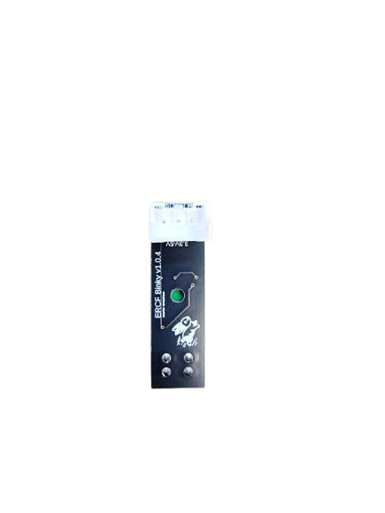
The Binky Encoder is a specialized device designed to convert binary data into a specific encoded format. This encoding process is essential for efficient data transmission, storage, and processing in digital systems. Manufactured by Binky, the Encoder is a versatile component widely used in communication systems, data compression, and digital signal processing applications.
Explore Projects Built with Binky Encoder

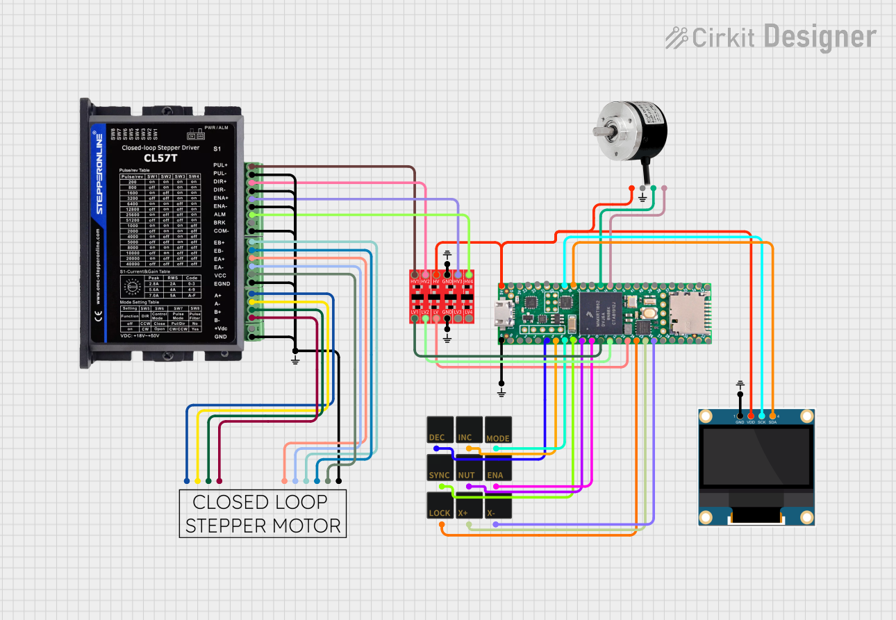
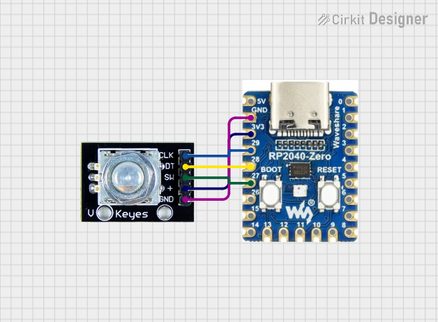
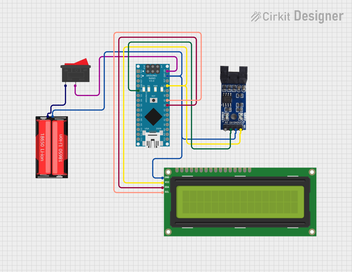
Explore Projects Built with Binky Encoder
Common Applications and Use Cases
- Data Transmission: Encoding binary data for error detection and correction in communication systems.
- Digital Signal Processing: Converting raw binary data into encoded formats for efficient processing.
- Data Storage: Encoding data to optimize storage space and ensure data integrity.
- Microcontroller Interfaces: Used in conjunction with microcontrollers like Arduino for encoding sensor or input data.
Technical Specifications
The Binky Encoder is designed to operate efficiently in a variety of digital systems. Below are its key technical specifications:
General Specifications
| Parameter | Value |
|---|---|
| Manufacturer | Binky |
| Part ID | Encoder |
| Operating Voltage | 3.3V to 5V |
| Maximum Current | 20 mA |
| Operating Temperature | -40°C to 85°C |
| Encoding Format | Customizable (e.g., Gray Code, Binary) |
| Data Input Lines | 4, 8, or 16 (depending on model) |
| Data Output Lines | 4, 8, or 16 (depending on model) |
| Propagation Delay | < 10 ns |
Pin Configuration and Descriptions
The Binky Encoder comes in a standard 16-pin DIP (Dual Inline Package) configuration. Below is the pinout description:
| Pin Number | Name | Description |
|---|---|---|
| 1 | VCC | Power supply input (3.3V to 5V) |
| 2 | GND | Ground connection |
| 3-10 | D0-D7 | Data input lines (binary input) |
| 11-14 | Q0-Q3 | Encoded data output lines |
| 15 | ENABLE | Enable pin (active HIGH to enable encoding) |
| 16 | NC | Not connected |
Usage Instructions
The Binky Encoder is straightforward to use in digital circuits. Follow the steps below to integrate it into your design:
Step 1: Power Connection
- Connect the VCC pin to a 3.3V or 5V power supply, depending on your system's voltage level.
- Connect the GND pin to the ground of your circuit.
Step 2: Data Input
- Connect your binary data source (e.g., switches, sensors, or microcontroller outputs) to the D0-D7 input pins.
- Ensure that the input data lines are stable and within the voltage range of the encoder.
Step 3: Enable Encoding
- Use the ENABLE pin to activate the encoder. Set this pin HIGH to enable encoding functionality.
Step 4: Data Output
- The encoded data will be available on the Q0-Q3 output pins. Connect these pins to your desired destination, such as a microcontroller or storage device.
Important Considerations
- Input Stability: Ensure that the input data is stable before enabling the encoder to avoid glitches in the output.
- Decoupling Capacitor: Place a 0.1 µF decoupling capacitor between VCC and GND to filter out noise.
- Unused Pins: If fewer input lines are used, tie unused input pins (D4-D7) to GND to prevent floating inputs.
Example: Using the Binky Encoder with Arduino UNO
Below is an example of how to use the Binky Encoder with an Arduino UNO to encode 4-bit binary data:
// Define input pins for binary data
const int dataPins[] = {2, 3, 4, 5}; // D0-D3 connected to Arduino pins 2-5
// Define output pins for encoded data
const int outputPins[] = {6, 7, 8, 9}; // Q0-Q3 connected to Arduino pins 6-9
// Define the ENABLE pin
const int enablePin = 10; // ENABLE connected to Arduino pin 10

void setup() {
  // Set data pins as inputs
  for (int i = 0; i < 4; i++) {
    pinMode(dataPins[i], INPUT);
  }
  // Set output pins as outputs
  for (int i = 0; i < 4; i++) {
    pinMode(outputPins[i], OUTPUT);
  }
  // Set ENABLE pin as output
  pinMode(enablePin, OUTPUT);
  // Enable the encoder
  digitalWrite(enablePin, HIGH);
}

void loop() {
  // Read binary data from input pins
  int binaryData = 0;
  for (int i = 0; i < 4; i++) {
    binaryData |= digitalRead(dataPins[i]) << i;
  }

  // Simulate encoding process (for demonstration purposes)
  int encodedData = binaryData ^ 0b1010; // Example encoding logic (XOR with 1010)

  // Output encoded data to output pins
  for (int i = 0; i < 4; i++) {
    digitalWrite(outputPins[i], (encodedData >> i) & 0x01);
  }

  delay(100); // Small delay for stability
}
Troubleshooting and FAQs
Common Issues
No Output on Q0-Q3 Pins
- Cause: The ENABLE pin is not set HIGH.
- Solution: Ensure the ENABLE pin is connected to a HIGH signal.
Incorrect Encoded Output
- Cause: Unstable or floating input pins.
- Solution: Verify that all input pins are properly connected and stable. Tie unused input pins to GND.
High Power Consumption
- Cause: Noise or oscillations on the power supply.
- Solution: Add a decoupling capacitor (0.1 µF) between VCC and GND.
Overheating
- Cause: Exceeding the maximum voltage or current ratings.
- Solution: Ensure the power supply voltage is within the 3.3V to 5V range and the current does not exceed 20 mA.
FAQs
Q1: Can the Binky Encoder handle 16-bit data?
A1: Yes, the Binky Encoder supports models with 16 input and output lines. Refer to the specific model's datasheet for details.
Q2: Is the encoding format customizable?
A2: Yes, the encoding format can be customized based on your application. Consult the manufacturer for advanced configuration options.
Q3: Can I use the Binky Encoder with a 3.3V microcontroller?
A3: Yes, the encoder operates at both 3.3V and 5V, making it compatible with a wide range of microcontrollers.
Q4: What is the propagation delay of the encoder?
A4: The propagation delay is less than 10 ns, ensuring high-speed operation in digital systems.