How to Use TP4056: Examples, Pinouts, and Specs
Introduction
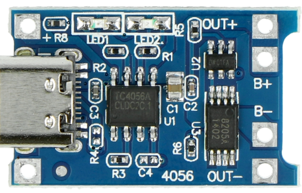
The TP4056 is a lithium-ion battery charger IC manufactured by Makers, with the part ID TP4036. It is designed to provide a constant current/constant voltage (CC/CV) charging profile, making it ideal for charging single-cell lithium-ion batteries. The IC integrates advanced features such as over-voltage protection, under-voltage lockout, and thermal regulation, ensuring safe and efficient charging.
Explore Projects Built with TP4056


Explore Projects Built with TP4056
Common Applications and Use Cases
- Charging single-cell lithium-ion or lithium-polymer batteries
- Power banks and portable battery packs
- USB-powered charging circuits
- Wearable devices and IoT applications
- DIY electronics projects
Technical Specifications
The TP4056 is a highly efficient and compact charging IC. Below are its key technical specifications:
| Parameter | Value |
|---|---|
| Input Voltage Range | 4.0V to 8.0V |
| Charging Voltage | 4.2V ± 1% |
| Maximum Charging Current | 1A (adjustable via external resistor) |
| Charging Method | Constant Current/Constant Voltage (CC/CV) |
| Operating Temperature Range | -40°C to +85°C |
| Standby Current | < 2µA |
| Thermal Regulation | Automatically reduces charge current to prevent overheating |
| Protection Features | Over-voltage, under-voltage lockout, reverse polarity, and thermal shutdown |
Pin Configuration and Descriptions
The TP4056 IC typically comes in an 8-pin SOP package. Below is the pin configuration and description:
| Pin Number | Pin Name | Description |
|---|---|---|
| 1 | TEMP | Temperature sense input. Connect to a thermistor for battery temperature monitoring. |
| 2 | PROG | Programs the charging current via an external resistor. |
| 3 | GND | Ground connection. |
| 4 | VCC | Input supply voltage (4.0V to 8.0V). |
| 5 | BAT | Battery connection pin. Connect directly to the positive terminal of the battery. |
| 6 | STDBY | Open-drain status output. Indicates charging status (low = charging, high = standby). |
| 7 | CHRG | Open-drain status output. Indicates charging in progress (low = charging). |
| 8 | CE | Chip enable. Active low. Pull low to enable the IC, or high to disable it. |
Usage Instructions
How to Use the TP4056 in a Circuit
- Power Supply: Connect a regulated DC power supply (4.0V to 8.0V) to the VCC pin. A USB port can also be used as the power source.
- Battery Connection: Connect the positive terminal of the lithium-ion battery to the BAT pin and the negative terminal to GND.
- Programming Charging Current: Use an external resistor (RPROG) connected to the PROG pin to set the desired charging current. The charging current can be calculated using the formula: [ I_{CHG} = \frac{1200}{R_{PROG}} ] where ( R_{PROG} ) is in kΩ and ( I_{CHG} ) is in mA.
- Status Monitoring: Use the CHRG and STDBY pins to monitor the charging status. These pins can be connected to LEDs for visual indication.
- Temperature Monitoring: Connect a thermistor to the TEMP pin for battery temperature monitoring. If not used, connect TEMP to GND.
Important Considerations and Best Practices
- Ensure the input voltage does not exceed 8.0V to avoid damaging the IC.
- Use a heat sink or proper PCB layout to dissipate heat during high-current charging.
- Place a decoupling capacitor (e.g., 1µF) close to the VCC pin to stabilize the input voltage.
- Use a Schottky diode at the input to prevent reverse polarity damage.
- Avoid using the TP4056 for batteries with a capacity below 500mAh, as the charging current may be too high.
Example: Connecting the TP4056 to an Arduino UNO
The TP4056 can be used with an Arduino UNO to monitor the charging status. Below is an example code snippet:
// TP4056 Charging Status Monitoring with Arduino UNO
// Connect CHRG pin to Arduino pin 2 and STDBY pin to Arduino pin 3

const int chrgPin = 2;  // CHRG pin of TP4056
const int stdbyPin = 3; // STDBY pin of TP4056

void setup() {
  pinMode(chrgPin, INPUT);
  pinMode(stdbyPin, INPUT);
  Serial.begin(9600);
}

void loop() {
  int chrgStatus = digitalRead(chrgPin);  // Read CHRG pin status
  int stdbyStatus = digitalRead(stdbyPin); // Read STDBY pin status

  if (chrgStatus == LOW) {
    Serial.println("Battery is charging...");
  } else if (stdbyStatus == HIGH) {
    Serial.println("Battery is fully charged or in standby mode.");
  } else {
    Serial.println("No battery connected or error.");
  }

  delay(1000); // Wait for 1 second before checking again
}
Troubleshooting and FAQs
Common Issues and Solutions
The battery is not charging.
- Solution: Check the input voltage at the VCC pin. Ensure it is within the 4.0V to 8.0V range.
- Verify the battery connection to the BAT and GND pins.
- Ensure the CE pin is pulled low to enable the IC.
The IC overheats during charging.
- Solution: Reduce the charging current by increasing the value of the RPROG resistor.
- Improve heat dissipation by adding a heat sink or using a PCB with good thermal management.
The CHRG and STDBY LEDs do not light up.
- Solution: Check the connections to the CHRG and STDBY pins.
- Verify that the LEDs are connected with the correct polarity and have appropriate current-limiting resistors.
The charging current is too high or too low.
- Solution: Recalculate and adjust the RPROG resistor value using the formula provided.
FAQs
Q: Can the TP4056 charge multiple batteries in series?
A: No, the TP4056 is designed for single-cell lithium-ion batteries only. Charging multiple cells in series requires a specialized multi-cell charger.
Q: What happens if the input voltage exceeds 8.0V?
A: The IC may be damaged. Always ensure the input voltage is within the specified range.
Q: Can I use the TP4056 without a thermistor?
A: Yes, if temperature monitoring is not required, connect the TEMP pin to GND.
Q: How do I adjust the charging voltage?
A: The charging voltage is fixed at 4.2V and cannot be adjusted. For other voltages, consider using a different IC.
This concludes the documentation for the TP4056.