Cirkit Designer Logo
Cirkit Designer
Your all-in-one circuit design IDE
Home / 
Component Documentation

How to Use SparkFun Qwiic 6DoF LSM6DSO: Examples, Pinouts, and Specs

Image of SparkFun Qwiic 6DoF LSM6DSO
Cirkit Designer LogoDesign with SparkFun Qwiic 6DoF LSM6DSO in Cirkit Designer

Introduction

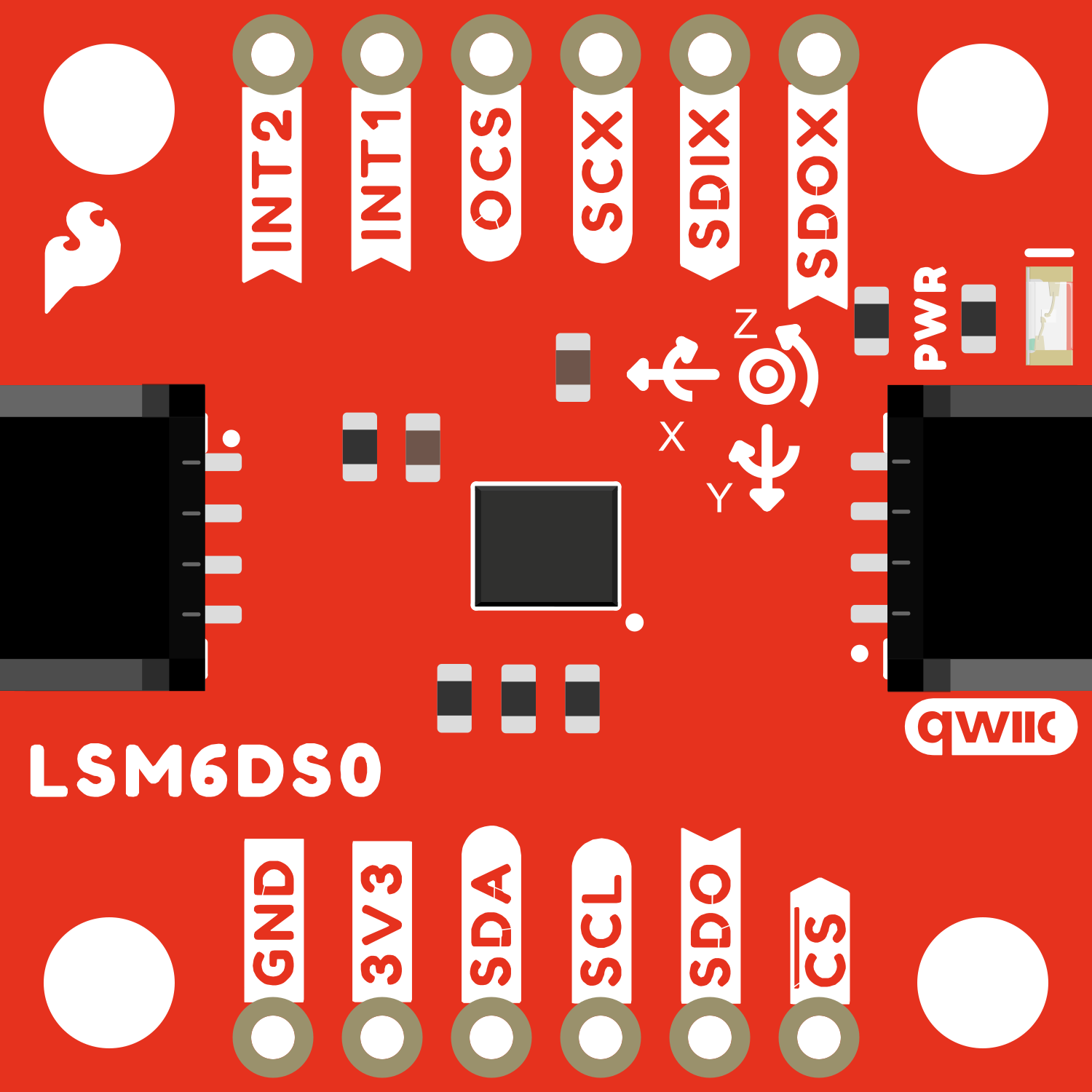
The SparkFun Qwiic 6DoF LSM6DSO is a versatile and powerful sensor module that combines a 3-axis accelerometer and a 3-axis gyroscope into a single package. This sensor is ideal for applications requiring motion detection, such as gesture control, gaming, inertial measurement units (IMUs), and navigation systems. Its Qwiic connector system enables easy daisy-chaining and quick prototyping without the need for soldering.

Explore Projects Built with SparkFun Qwiic 6DoF LSM6DSO

Use Cirkit Designer to design, explore, and prototype these projects online. Some projects support real-time simulation. Click "Open Project" to start designing instantly!
Adafruit MPU6050 and VL6180X Sensor Interface with Servo Control
Image of wire: A project utilizing SparkFun Qwiic 6DoF LSM6DSO in a practical application
This circuit features an Adafruit QT Py microcontroller interfaced with an Adafruit MPU6050 6-axis accelerometer/gyroscope and an Adafruit VL6180X Time of Flight (ToF) distance sensor, both connected via I2C communication. The QT Py also controls a Servomotor SG90, likely for physical actuation based on sensor inputs. The embedded code initializes the sensors, reads their data, and outputs the readings to a serial monitor, with the potential for motion control based on the sensor feedback.
Cirkit Designer LogoOpen Project in Cirkit Designer
Arduino UNO-Based IMU and Bluetooth Communication System
Image of New one: A project utilizing SparkFun Qwiic 6DoF LSM6DSO in a practical application
This circuit features an Arduino UNO microcontroller interfaced with a Bluetooth HC-06 module for wireless communication and an Adafruit BNO085 9-DOF Orientation IMU for motion sensing. The Arduino handles data acquisition from the IMU via I2C and communicates the data wirelessly through the Bluetooth module.
Cirkit Designer LogoOpen Project in Cirkit Designer
Raspberry Pi 5-Based Multi-Sensor IMU System with MPU-6050 and LSM303c
Image of GRS: A project utilizing SparkFun Qwiic 6DoF LSM6DSO in a practical application
This circuit integrates a Raspberry Pi 5 with multiple sensors, including an MPU-6050 accelerometer and gyroscope, and an LSM303c 6DOF IMU, to collect and process motion and orientation data. The Raspberry Pi serves as the central processing unit, interfacing with the sensors via GPIO pins and providing power to them.
Cirkit Designer LogoOpen Project in Cirkit Designer
SparkFun Pro Micro Based Motion Tracking System with BMI160 and EEPROM Data Logging
Image of Basic Arduino Sparkfun Pro Micro + BMI160: A project utilizing SparkFun Qwiic 6DoF LSM6DSO in a practical application
This circuit is designed for motion sensing and data logging applications. It features a SparkFun Pro Micro microcontroller interfaced with a BMI160 6DOF sensor for motion detection and two 24LC512 EEPROM chips for extended data storage. The microcontroller reads gyroscopic and accelerometer data from the BMI160 sensor, processes it, and stores it in the EEPROM, with power supplied by a Polymer Lithium Ion Battery.
Cirkit Designer LogoOpen Project in Cirkit Designer

Explore Projects Built with SparkFun Qwiic 6DoF LSM6DSO

Use Cirkit Designer to design, explore, and prototype these projects online. Some projects support real-time simulation. Click "Open Project" to start designing instantly!
Image of wire: A project utilizing SparkFun Qwiic 6DoF LSM6DSO in a practical application
Adafruit MPU6050 and VL6180X Sensor Interface with Servo Control
This circuit features an Adafruit QT Py microcontroller interfaced with an Adafruit MPU6050 6-axis accelerometer/gyroscope and an Adafruit VL6180X Time of Flight (ToF) distance sensor, both connected via I2C communication. The QT Py also controls a Servomotor SG90, likely for physical actuation based on sensor inputs. The embedded code initializes the sensors, reads their data, and outputs the readings to a serial monitor, with the potential for motion control based on the sensor feedback.
Cirkit Designer LogoOpen Project in Cirkit Designer
Image of New one: A project utilizing SparkFun Qwiic 6DoF LSM6DSO in a practical application
Arduino UNO-Based IMU and Bluetooth Communication System
This circuit features an Arduino UNO microcontroller interfaced with a Bluetooth HC-06 module for wireless communication and an Adafruit BNO085 9-DOF Orientation IMU for motion sensing. The Arduino handles data acquisition from the IMU via I2C and communicates the data wirelessly through the Bluetooth module.
Cirkit Designer LogoOpen Project in Cirkit Designer
Image of GRS: A project utilizing SparkFun Qwiic 6DoF LSM6DSO in a practical application
Raspberry Pi 5-Based Multi-Sensor IMU System with MPU-6050 and LSM303c
This circuit integrates a Raspberry Pi 5 with multiple sensors, including an MPU-6050 accelerometer and gyroscope, and an LSM303c 6DOF IMU, to collect and process motion and orientation data. The Raspberry Pi serves as the central processing unit, interfacing with the sensors via GPIO pins and providing power to them.
Cirkit Designer LogoOpen Project in Cirkit Designer
Image of Basic Arduino Sparkfun Pro Micro + BMI160: A project utilizing SparkFun Qwiic 6DoF LSM6DSO in a practical application
SparkFun Pro Micro Based Motion Tracking System with BMI160 and EEPROM Data Logging
This circuit is designed for motion sensing and data logging applications. It features a SparkFun Pro Micro microcontroller interfaced with a BMI160 6DOF sensor for motion detection and two 24LC512 EEPROM chips for extended data storage. The microcontroller reads gyroscopic and accelerometer data from the BMI160 sensor, processes it, and stores it in the EEPROM, with power supplied by a Polymer Lithium Ion Battery.
Cirkit Designer LogoOpen Project in Cirkit Designer

Technical Specifications

Key Features

  • Accelerometer Ranges: ±2, ±4, ±8, ±16 g
  • Gyroscope Ranges: ±125, ±250, ±500, ±1000, ±2000 dps (degrees per second)
  • Interface: I2C (Qwiic)
  • Supply Voltage: 1.71V to 3.6V
  • Current Consumption: 0.9 mA (typical)
  • Communication Protocol: I2C (up to 400 kHz)
  • Operating Temperature Range: -40°C to +85°C

Pin Configuration and Descriptions

Pin Name Description
GND Ground
VCC Supply Voltage (1.71V to 3.6V)
SDA I2C Data Line
SCL I2C Clock Line
INT1 Interrupt 1 (configurable)
INT2 Interrupt 2 (configurable)
AD0/SDO I2C Address Selection/Serial Data Out for SPI
CS Chip Select for SPI (not used in Qwiic)

Usage Instructions

Integration with a Circuit

  1. Powering the Sensor: Connect the VCC pin to a power supply within the 1.71V to 3.6V range and GND to the ground.
  2. I2C Communication: Connect the SDA and SCL pins to the I2C data and clock lines, respectively. If using with a Qwiic system, simply connect the Qwiic cable to the sensor and your microcontroller's Qwiic connector.
  3. Addressing: The default I2C address is 0x6A. If you need to change the address, you can connect the AD0/SDO pin to VCC or GND.

Best Practices

  • Ensure that the power supply is within the specified voltage range to prevent damage.
  • Use pull-up resistors on the I2C lines if they are not already present on your microcontroller board.
  • When using multiple I2C devices, ensure that each device has a unique address.
  • Avoid physical shocks and vibrations that could affect the sensor readings.

Example Code for Arduino UNO

#include <Wire.h> // Include the I2C library (required)

// LSM6DSO I2C address is 0x6A if SA0 pin is GND, 0x6B if SA0 pin is VCC
#define LSM6DSO_ADDRESS 0x6A

// Register addresses
#define WHO_AM_I_REG 0x0F
#define CTRL1_XL 0x10
#define CTRL2_G 0x11
#define OUTX_L_G 0x22

// Initialize I2C communication
void setup() {
  Wire.begin(); // Join the I2C bus as master
  Serial.begin(9600); // Start serial communication at 9600 baud rate
  
  // Check if LSM6DSO is connected properly
  Wire.beginTransmission(LSM6DSO_ADDRESS);
  Wire.write(WHO_AM_I_REG);
  Wire.endTransmission();
  Wire.requestFrom(LSM6DSO_ADDRESS, 1);
  if(Wire.read() == 0x6C) {
    Serial.println("LSM6DSO is online...");
  } else {
    Serial.println("Device not found. Check wiring.");
  }
  
  // Configure the accelerometer and gyroscope
  Wire.beginTransmission(LSM6DSO_ADDRESS);
  Wire.write(CTRL1_XL);
  Wire.write(0x50); // 1.66 kHz, 2g, normal mode
  Wire.write(CTRL2_G);
  Wire.write(0x50); // 1.66 kHz, 250 dps, normal mode
  Wire.endTransmission();
}

// Read sensor data
void loop() {
  int16_t gx, gy, gz;
  
  Wire.beginTransmission(LSM6DSO_ADDRESS);
  Wire.write(OUTX_L_G);
  Wire.endTransmission();
  Wire.requestFrom(LSM6DSO_ADDRESS, 6);
  
  if(Wire.available() == 6) {
    gx = Wire.read() | Wire.read() << 8;
    gy = Wire.read() | Wire.read() << 8;
    gz = Wire.read() | Wire.read() << 8;
    
    // Print the readings
    Serial.print("Gx: "); Serial.print(gx); Serial.print(" ");
    Serial.print("Gy: "); Serial.print(gy); Serial.print(" ");
    Serial.print("Gz: "); Serial.println(gz);
  }
  
  delay(1000); // Wait for a second before the next reading
}

Troubleshooting and FAQs

Common Issues

  • Sensor Not Detected: Ensure that the wiring is correct, and the power supply is within the specified range. Check the I2C address used in your code.
  • Inaccurate Readings: Make sure the sensor is placed on a stable surface without vibrations. Calibrate the sensor if necessary.
  • No Data on Serial Monitor: Confirm that the correct baud rate is set in the serial monitor and that the board is properly connected to the computer.

FAQs

Q: Can I use the LSM6DSO with a 5V microcontroller? A: Yes, but ensure that the sensor's VCC is connected to a voltage within its operating range (1.71V to 3.6V). Use logic level converters for I2C lines if necessary.

Q: How can I change the I2C address of the sensor? A: The I2C address can be changed by connecting the AD0/SDO pin to VCC or GND.

Q: What is the purpose of the INT1 and INT2 pins? A: These pins can be configured to output interrupt signals for various functions such as data ready, free-fall detection, or orientation change.

Q: How do I calibrate the sensor? A: Calibration involves capturing readings at a known orientation and adjusting subsequent readings accordingly. This process can be complex and may require additional software or algorithms.

For further assistance, please refer to the SparkFun Qwiic 6DoF LSM6DSO datasheet or contact technical support.