How to Use Grove O2 sensor: Examples, Pinouts, and Specs
Introduction
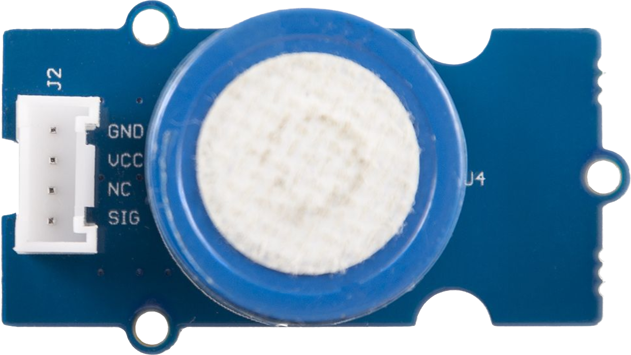
The Grove O2 Sensor is a device designed to measure the concentration of oxygen in the air. It employs electrochemical technology to deliver precise and reliable readings, making it an essential tool for applications requiring oxygen level monitoring. This sensor is part of the Grove ecosystem, which simplifies prototyping and integration with its plug-and-play modular design.
Explore Projects Built with Grove O2 sensor
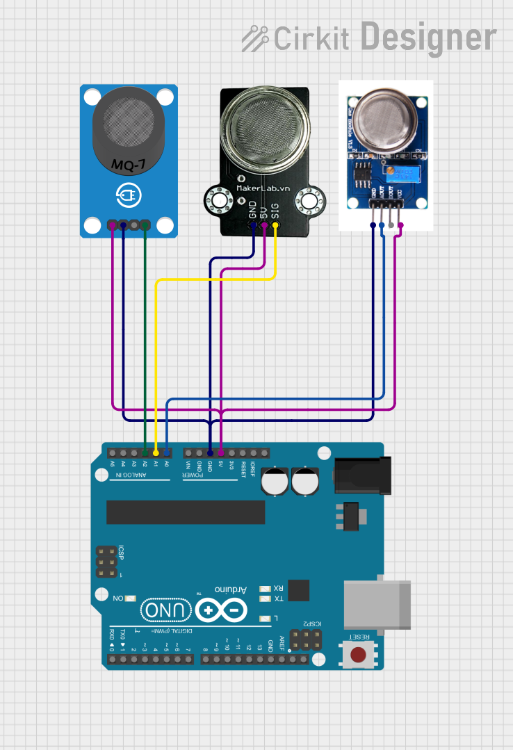

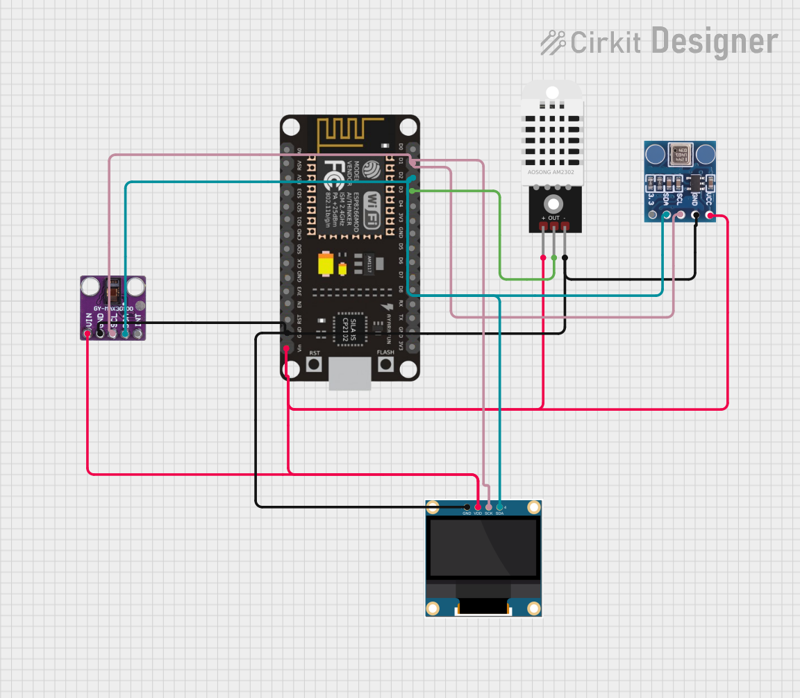
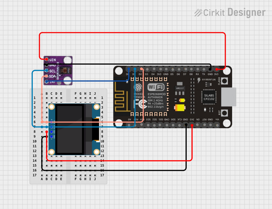
Explore Projects Built with Grove O2 sensor
Common Applications and Use Cases
- Environmental monitoring (e.g., air quality analysis)
- Industrial safety systems
- Medical and health devices
- Laboratory experiments
- Educational projects and prototyping
Technical Specifications
The following table outlines the key technical details of the Grove O2 Sensor:
| Parameter | Value |
|---|---|
| Operating Voltage | 3.3V to 5.5V |
| Output Signal | Analog voltage |
| Measurement Range | 0% to 25% oxygen concentration |
| Response Time | ≤ 15 seconds |
| Operating Temperature | -20°C to 50°C |
| Operating Humidity | 15% to 90% RH (non-condensing) |
| Lifespan | > 2 years (under normal conditions) |
| Dimensions | 20mm x 40mm |
Pin Configuration and Descriptions
The Grove O2 Sensor has a 4-pin Grove connector. The pin configuration is as follows:
| Pin | Name | Description |
|---|---|---|
| 1 | VCC | Power supply input (3.3V to 5.5V) |
| 2 | GND | Ground |
| 3 | NC | Not connected |
| 4 | SIG | Analog output signal proportional to oxygen level |
Usage Instructions
How to Use the Grove O2 Sensor in a Circuit
- Connect the Sensor: Use a Grove cable to connect the sensor to an analog input port on a Grove Base Shield or Grove-compatible microcontroller (e.g., Arduino UNO).
- Power the Sensor: Ensure the microcontroller provides a stable voltage of 3.3V or 5V to the sensor.
- Read the Output: The sensor outputs an analog voltage signal proportional to the oxygen concentration. Use an analog-to-digital converter (ADC) to read the signal.
Important Considerations and Best Practices
- Warm-Up Time: Allow the sensor to stabilize for a few minutes after powering it on for accurate readings.
- Calibration: Periodically calibrate the sensor using a known oxygen concentration for precise measurements.
- Environmental Conditions: Avoid exposing the sensor to extreme temperatures, humidity, or corrosive gases, as these can affect its performance and lifespan.
- Signal Processing: Use appropriate scaling and conversion formulas to interpret the analog signal as oxygen concentration (refer to the sensor's datasheet for details).
Example Code for Arduino UNO
Below is an example Arduino sketch to read data from the Grove O2 Sensor:
// Include necessary libraries
const int O2SensorPin = A0; // Analog pin connected to the sensor's SIG pin

void setup() {
  Serial.begin(9600); // Initialize serial communication at 9600 baud
  pinMode(O2SensorPin, INPUT); // Set the sensor pin as input
}

void loop() {
  int sensorValue = analogRead(O2SensorPin); // Read the analog value
  // Convert the analog value to voltage (assuming 5V reference)
  float voltage = sensorValue * (5.0 / 1023.0);

  // Calculate oxygen concentration (refer to sensor datasheet for formula)
  float oxygenConcentration = (voltage / 5.0) * 25.0; // Example conversion

  // Print the oxygen concentration to the Serial Monitor
  Serial.print("Oxygen Concentration: ");
  Serial.print(oxygenConcentration);
  Serial.println(" %");

  delay(1000); // Wait for 1 second before the next reading
}
Troubleshooting and FAQs
Common Issues and Solutions
No Output Signal:
- Cause: Loose or incorrect connections.
- Solution: Verify that the Grove cable is securely connected to both the sensor and the microcontroller.
Inaccurate Readings:
- Cause: Sensor not calibrated or exposed to extreme environmental conditions.
- Solution: Calibrate the sensor using a known oxygen concentration and ensure it operates within the specified temperature and humidity range.
Slow Response Time:
- Cause: Sensor not warmed up.
- Solution: Allow the sensor to stabilize for a few minutes after powering it on.
Fluctuating Readings:
- Cause: Electrical noise or unstable power supply.
- Solution: Use a decoupling capacitor near the sensor's power pins and ensure a stable power source.
FAQs
Q: Can the Grove O2 Sensor measure oxygen concentration in liquids?
A: No, this sensor is designed to measure oxygen concentration in the air only.
Q: How often should the sensor be calibrated?
A: Calibration frequency depends on usage conditions. For critical applications, calibrate the sensor monthly or as recommended in the datasheet.
Q: Can I use the sensor with a 3.3V microcontroller?
A: Yes, the sensor operates within a voltage range of 3.3V to 5.5V, making it compatible with 3.3V systems.
Q: What is the lifespan of the sensor?
A: Under normal operating conditions, the sensor has a lifespan of over 2 years.