
How to Use Arduino Nano ESP32: Examples, Pinouts, and Specs
 Design with Arduino Nano ESP32 in Cirkit Designer
Introduction
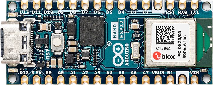
The Arduino Nano ESP32 is a compact and versatile microcontroller board developed by Arduino, featuring the powerful ESP32-S3 microcontroller. This board combines the ease of use of the Arduino ecosystem with the advanced capabilities of the ESP32, including Wi-Fi and Bluetooth connectivity. Its small form factor makes it ideal for IoT applications, wearable devices, and other projects requiring wireless communication and low power consumption.
Explore Projects Built with Arduino Nano ESP32
 Open Project in Cirkit Designer
 Open Project in Cirkit Designer
 Open Project in Cirkit Designer
 Open Project in Cirkit Designer
Explore Projects Built with Arduino Nano ESP32
Open Project in Cirkit DesignerOpen Project in Cirkit DesignerOpen Project in Cirkit DesignerOpen Project in Cirkit DesignerCommon Applications and Use Cases
- Internet of Things (IoT) devices
- Home automation systems
- Wireless sensor networks
- Wearable technology
- Robotics and automation
- Prototyping and educational projects
Technical Specifications
The following table outlines the key technical specifications of the Arduino Nano ESP32:
| Specification | Details |
|---|---|
| Microcontroller | ESP32-S3 (Xtensa® 32-bit LX7 dual-core processor) |
| Operating Voltage | 3.3V |
| Input Voltage (VIN) | 5V (via USB-C or VIN pin) |
| Digital I/O Pins | 14 (including PWM support) |
| Analog Input Pins | 8 |
| Analog Output Pins | 1 (DAC) |
| Flash Memory | 8MB |
| SRAM | 512KB |
| Connectivity | Wi-Fi 802.11 b/g/n, Bluetooth 5.0 (LE) |
| USB Interface | USB-C (for programming and power) |
| Communication Protocols | UART, SPI, I2C, I2S |
| Dimensions | 45mm x 18mm |
| Weight | 5g |
Pin Configuration and Descriptions
The Arduino Nano ESP32 features a 30-pin layout. Below is the pin configuration:
| Pin | Name | Type | Description |
|---|---|---|---|
| 1 | VIN | Power Input | External power input (5V). |
| 2 | GND | Ground | Ground connection. |
| 3 | 3V3 | Power Output | 3.3V regulated output. |
| 4-11 | D0-D7 | Digital I/O | General-purpose digital pins (PWM capable). |
| 12-13 | RX, TX | UART | Serial communication pins. |
| 14-21 | A0-A7 | Analog Input | Analog input pins (12-bit ADC). |
| 22 | DAC | Analog Output | Digital-to-Analog Converter (DAC) output. |
| 23-24 | SCL, SDA | I2C | I2C communication pins. |
| 25-26 | MOSI, MISO | SPI | SPI communication pins. |
| 27 | SCK | SPI | SPI clock pin. |
| 28 | EN | Enable | Enable pin to reset the board. |
| 29 | BOOT | Boot | Boot mode selection pin. |
| 30 | USB-C | Power/USB | USB-C port for programming and power. |
Usage Instructions
How to Use the Arduino Nano ESP32 in a Circuit
Powering the Board:
- Connect the board to your computer via the USB-C port for programming and power.
- Alternatively, supply 5V to the VIN pin for external power.
Programming the Board:
- Install the Arduino IDE and add the ESP32 board package via the Board Manager.
- Select "Arduino Nano ESP32" from the Tools > Board menu.
- Connect the board to your computer and upload your sketch.
Connecting Peripherals:
- Use the digital I/O pins for sensors, actuators, or other devices.
- For analog sensors, connect them to the analog input pins (A0-A7).
- Use the I2C (SCL, SDA) or SPI (MOSI, MISO, SCK) pins for communication with other devices.
Important Considerations and Best Practices
- Ensure the input voltage does not exceed 5V to avoid damaging the board.
- Use level shifters when interfacing with 5V logic devices, as the board operates at 3.3V.
- Avoid drawing excessive current from the 3.3V pin, as it is limited by the onboard regulator.
- Use proper decoupling capacitors when connecting external components to reduce noise.
Example Code for Arduino Nano ESP32 with Arduino IDE
The following example demonstrates how to connect the Arduino Nano ESP32 to a Wi-Fi network and print the IP address to the Serial Monitor:
#include <WiFi.h> // Include the WiFi library for ESP32

// Replace with your network credentials
const char* ssid = "Your_SSID";       // Your Wi-Fi network name
const char* password = "Your_PASSWORD"; // Your Wi-Fi network password

void setup() {
  Serial.begin(115200); // Initialize serial communication at 115200 baud
  delay(1000);          // Wait for the Serial Monitor to initialize

  Serial.println("Connecting to Wi-Fi...");
  WiFi.begin(ssid, password); // Start connecting to Wi-Fi

  // Wait until the board connects to Wi-Fi
  while (WiFi.status() != WL_CONNECTED) {
    delay(500);
    Serial.print(".");
  }

  Serial.println("\nConnected to Wi-Fi!");
  Serial.print("IP Address: ");
  Serial.println(WiFi.localIP()); // Print the board's IP address
}

void loop() {
  // Add your main code here
}
Troubleshooting and FAQs
Common Issues and Solutions
The board is not detected by the Arduino IDE:
- Ensure the correct USB driver is installed for the ESP32.
- Check that the USB cable is functional and supports data transfer.
- Verify that the correct board and port are selected in the Arduino IDE.
Wi-Fi connection fails:
- Double-check the SSID and password for your Wi-Fi network.
- Ensure the Wi-Fi network is within range and not overloaded.
- Restart the board and try reconnecting.
Sketch upload fails:
- Press and hold the BOOT button while uploading the sketch.
- Ensure the correct COM port is selected in the Arduino IDE.
- Check for syntax errors in your code.
FAQs
Q: Can I power the Arduino Nano ESP32 with a battery?
A: Yes, you can power the board using a 3.7V LiPo battery connected to the VIN pin. Ensure the battery voltage does not exceed 5V.
Q: Does the board support OTA (Over-The-Air) updates?
A: Yes, the ESP32-S3 microcontroller supports OTA updates. You can implement OTA functionality in your sketches.
Q: Can I use the Arduino Nano ESP32 with MicroPython?
A: Yes, the ESP32-S3 is compatible with MicroPython. You can flash the MicroPython firmware to the board and use it for Python-based development.
Q: What is the maximum current output of the 3.3V pin?
A: The 3.3V pin can supply up to 500mA, depending on the input power source.
Q: How do I reset the board?
A: Press the EN (Enable) button to reset the board.