How to Use NB IoT 2 Click: Examples, Pinouts, and Specs
Introduction
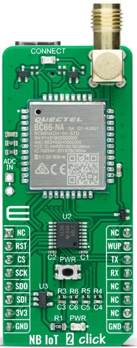
The NB IoT 2 Click (Manufacturer Part ID: MIKROE-4562) is a compact development board designed by MIKROE for Internet of Things (IoT) applications. It features a cellular module that supports Narrowband IoT (NB-IoT) technology, enabling low-power, wide-area connectivity for IoT devices. This makes it ideal for applications requiring reliable, long-range communication with minimal power consumption.
Explore Projects Built with NB IoT 2 Click
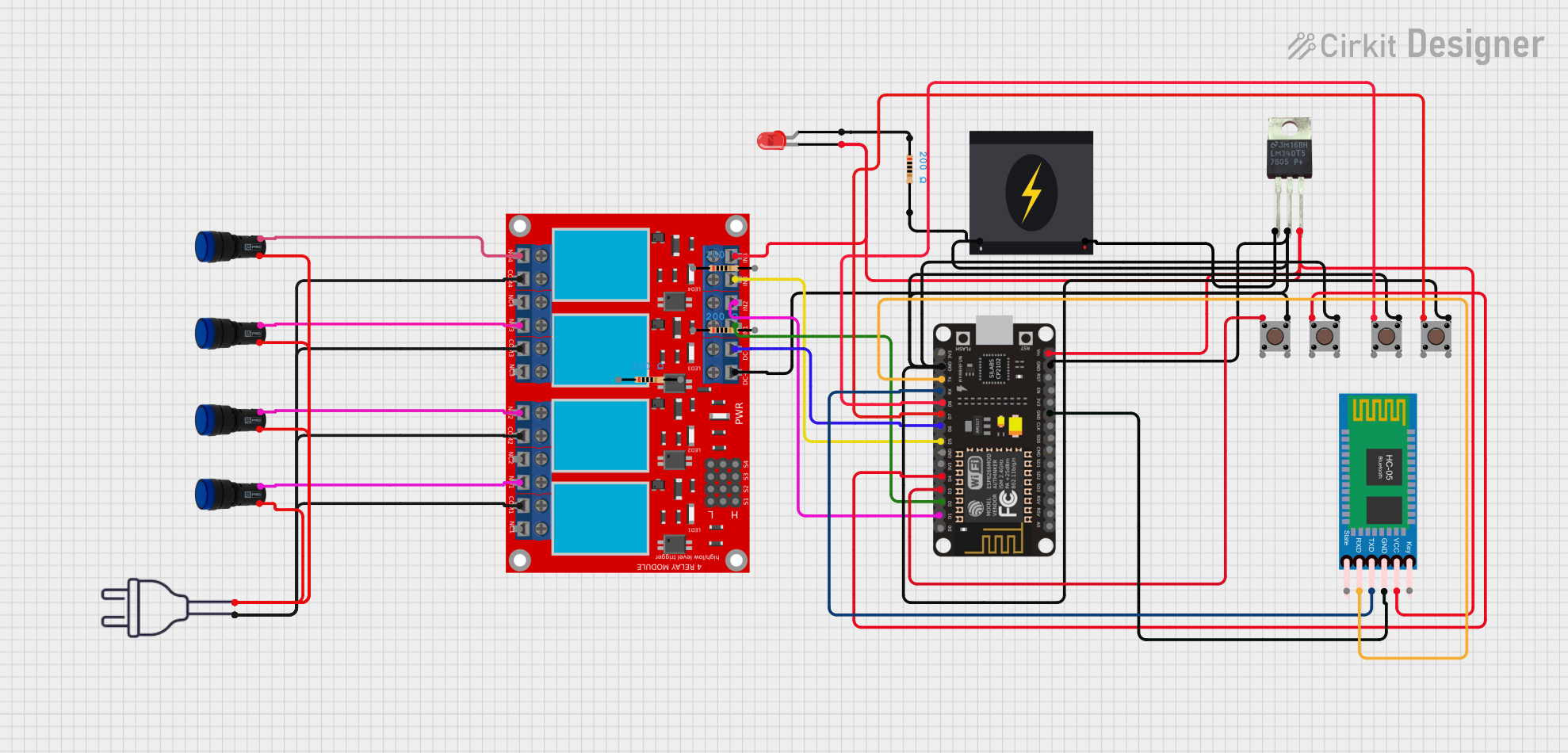
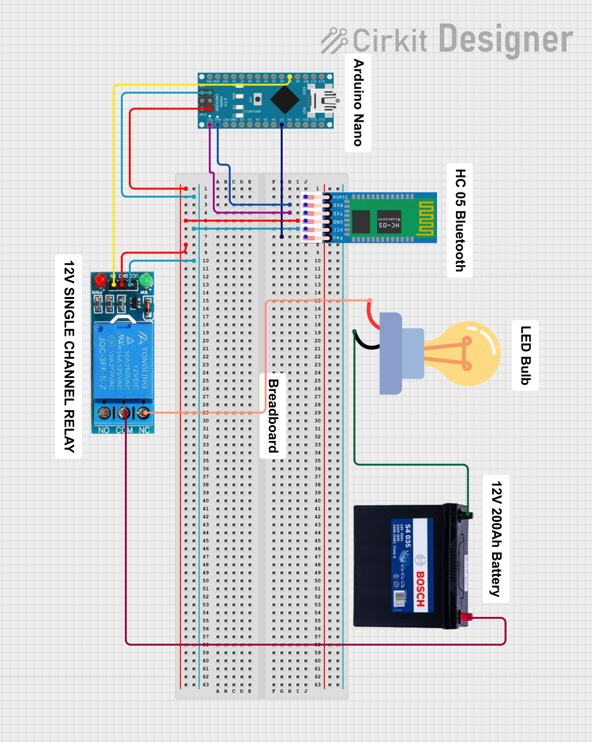
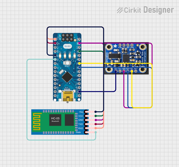

Explore Projects Built with NB IoT 2 Click
Common Applications
- Smart metering (e.g., water, gas, electricity)
- Asset tracking and fleet management
- Environmental monitoring (e.g., air quality sensors)
- Smart agriculture (e.g., soil moisture sensors)
- Industrial IoT (e.g., predictive maintenance)
Technical Specifications
Key Technical Details
| Parameter | Value |
|---|---|
| Cellular Module | Quectel BG95 |
| Communication Protocols | NB-IoT, LTE Cat M1, EGPRS |
| Operating Voltage | 3.3V |
| Power Consumption | Ultra-low power in idle mode (<1mA) |
| Interface | UART |
| Antenna Connector | U.FL |
| Dimensions | 42.9mm x 25.4mm |
| Operating Temperature | -40°C to +85°C |
Pin Configuration and Descriptions
The NB IoT 2 Click uses the mikroBUS™ standard pinout. Below is the pin configuration:
| Pin No. | Pin Name | Description |
|---|---|---|
| 1 | AN | Not connected |
| 2 | RST | Reset pin for the module |
| 3 | CS | Not connected |
| 4 | SCK | Not connected |
| 5 | MISO | Not connected |
| 6 | MOSI | Not connected |
| 7 | PWM | Not connected |
| 8 | INT | Interrupt pin |
| 9 | TX | UART Transmit |
| 10 | RX | UART Receive |
| 11 | SCL | Not connected |
| 12 | SDA | Not connected |
| 13 | 3.3V | Power supply (3.3V) |
| 14 | GND | Ground |
Usage Instructions
How to Use the Component in a Circuit
- Power Supply: Connect the NB IoT 2 Click to a 3.3V power source via the mikroBUS™ socket.
- UART Communication: Use the TX and RX pins to establish UART communication with a microcontroller or development board (e.g., Arduino UNO, Raspberry Pi, or STM32).
- Antenna Connection: Attach an external antenna to the U.FL connector for optimal signal reception.
- SIM Card: Insert a compatible NB-IoT SIM card into the onboard SIM card slot.
- Initialization: Configure the module using AT commands via UART to establish a connection with the cellular network.
Important Considerations and Best Practices
- Ensure the power supply is stable and within the specified range (3.3V).
- Use a high-quality antenna to maximize signal strength and reliability.
- Place the board in an area with good cellular coverage for optimal performance.
- Avoid exposing the board to extreme temperatures or humidity.
- Use proper UART settings (e.g., baud rate) as specified in the Quectel BG95 datasheet.
Example Code for Arduino UNO
Below is an example of how to initialize the NB IoT 2 Click with an Arduino UNO:
#include <SoftwareSerial.h>

// Define RX and TX pins for SoftwareSerial
SoftwareSerial nbIoTSerial(2, 3); // RX = Pin 2, TX = Pin 3

void setup() {
  // Initialize serial communication with the NB IoT 2 Click
  Serial.begin(9600); // Serial monitor for debugging
  nbIoTSerial.begin(9600); // UART communication with the module

  Serial.println("Initializing NB IoT 2 Click...");

  // Send AT command to check communication
  nbIoTSerial.println("AT");
  delay(1000);

  // Read response from the module
  while (nbIoTSerial.available()) {
    String response = nbIoTSerial.readString();
    Serial.println("Response: " + response);
  }
}

void loop() {
  // Example: Send data to the module
  nbIoTSerial.println("AT+CSQ"); // Check signal quality
  delay(2000);

  // Read and print the response
  while (nbIoTSerial.available()) {
    String response = nbIoTSerial.readString();
    Serial.println("Response: " + response);
  }
}
Note: Replace AT+CSQ with other AT commands as needed for your application. Refer to the Quectel BG95 AT Command Manual for a complete list of supported commands.
Troubleshooting and FAQs
Common Issues and Solutions
No Response from the Module
- Cause: Incorrect UART connection or baud rate.
- Solution: Verify the TX and RX connections and ensure the baud rate matches the module's default settings (9600 bps).
Poor Signal Quality
- Cause: Weak cellular coverage or poor antenna placement.
- Solution: Use a high-quality antenna and place the board in an area with better signal reception.
Module Not Connecting to Network
- Cause: Incorrect SIM card or network settings.
- Solution: Ensure the SIM card supports NB-IoT and is activated. Check the APN settings using the
AT+CGDCONTcommand.
High Power Consumption
- Cause: Module not entering low-power mode.
- Solution: Use the
AT+QSCLKcommand to enable sleep mode when the module is idle.
FAQs
Q: Can I use the NB IoT 2 Click with 5V microcontrollers?
A: No, the NB IoT 2 Click operates at 3.3V. Use a level shifter if interfacing with a 5V microcontroller.Q: What is the maximum data rate supported?
A: The maximum data rate depends on the network and mode (NB-IoT, LTE Cat M1, or EGPRS). Refer to the Quectel BG95 datasheet for detailed specifications.Q: How do I update the firmware of the module?
A: Firmware updates can be performed via the UART interface. Refer to the Quectel BG95 firmware update guide for detailed instructions.Q: Can I use this board for GPS applications?
A: No, the NB IoT 2 Click does not include GPS functionality. For GPS-enabled applications, consider using a module with integrated GNSS support.
This concludes the documentation for the NB IoT 2 Click. For further assistance, refer to the official MIKROE documentation or contact their support team.