How to Use 5A DC Motor Driver Module PWM Speed Remote Control Double H Bridge: Examples, Pinouts, and Specs
Introduction
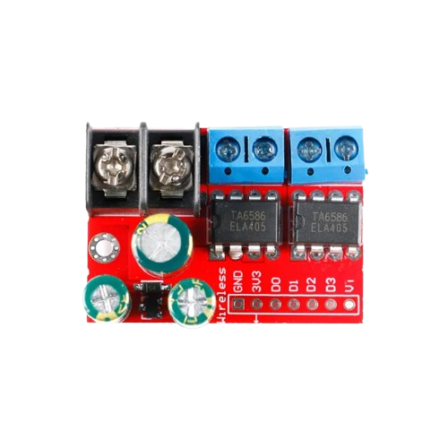
The 5A DC Motor Driver Module PWM Speed Remote Control Double H Bridge is a versatile motor driver designed to control the speed and direction of DC motors. It utilizes a double H-bridge configuration, enabling bidirectional control of motors with high efficiency. This module supports Pulse Width Modulation (PWM) for precise speed control and can handle currents up to 5A, making it suitable for a wide range of applications.
Explore Projects Built with 5A DC Motor Driver Module PWM Speed Remote Control Double H Bridge

Explore Projects Built with 5A DC Motor Driver Module PWM Speed Remote Control Double H Bridge
Common Applications and Use Cases
- Robotics and automation systems
- Electric vehicles and motorized toys
- Conveyor belts and industrial machinery
- DIY projects involving motor control
- Remote-controlled devices
Technical Specifications
Below are the key technical details of the module:
| Parameter | Value |
|---|---|
| Operating Voltage | 6V to 30V |
| Maximum Continuous Current | 5A |
| Peak Current | 10A (short duration) |
| Control Signal Voltage | 3.3V to 5V (logic level) |
| PWM Frequency | Up to 20 kHz |
| Motor Channels | 2 (dual H-bridge configuration) |
| Dimensions | 60mm x 50mm x 20mm |
| Weight | ~30g |
Pin Configuration and Descriptions
The module features the following pins for connection:
| Pin Name | Type | Description |
|---|---|---|
| VCC | Power Input | Connect to the positive terminal of the power supply (6V to 30V). |
| GND | Power Ground | Connect to the ground terminal of the power supply. |
| IN1 | Control Input | Logic input to control the direction of Motor A. |
| IN2 | Control Input | Logic input to control the direction of Motor A. |
| IN3 | Control Input | Logic input to control the direction of Motor B. |
| IN4 | Control Input | Logic input to control the direction of Motor B. |
| ENA | PWM Input | PWM signal input for speed control of Motor A. |
| ENB | PWM Input | PWM signal input for speed control of Motor B. |
| OUT1 | Motor Output | Connect to one terminal of Motor A. |
| OUT2 | Motor Output | Connect to the other terminal of Motor A. |
| OUT3 | Motor Output | Connect to one terminal of Motor B. |
| OUT4 | Motor Output | Connect to the other terminal of Motor B. |
Usage Instructions
How to Use the Component in a Circuit
- Power Supply: Connect the VCC pin to a power source (6V to 30V) and the GND pin to ground.
- Motor Connections: Connect the motor terminals to the OUT1/OUT2 pins for Motor A and OUT3/OUT4 pins for Motor B.
- Control Signals:
- Use IN1 and IN2 to control the direction of Motor A.
- Use IN3 and IN4 to control the direction of Motor B.
- Apply a PWM signal to ENA and ENB for speed control of Motor A and Motor B, respectively.
- Logic Levels: Ensure the control signals (IN1, IN2, IN3, IN4, ENA, ENB) are within the 3.3V to 5V range.
Important Considerations and Best Practices
- Heat Dissipation: The module may heat up during operation. Use a heat sink or active cooling if operating near the maximum current limit.
- Power Supply: Ensure the power supply can provide sufficient current for the motors and the module.
- PWM Frequency: Use a PWM frequency within the module's supported range (up to 20 kHz) for optimal performance.
- Reverse Polarity Protection: Verify the polarity of the power supply to avoid damage to the module.
Example Code for Arduino UNO
Below is an example of how to control a single motor using the module and an Arduino UNO:
// Define motor control pins
const int IN1 = 7;  // Direction control for Motor A
const int IN2 = 8;  // Direction control for Motor A
const int ENA = 9;  // PWM speed control for Motor A

void setup() {
  // Set motor control pins as outputs
  pinMode(IN1, OUTPUT);
  pinMode(IN2, OUTPUT);
  pinMode(ENA, OUTPUT);
}

void loop() {
  // Rotate motor forward at 50% speed
  digitalWrite(IN1, HIGH);  // Set IN1 high
  digitalWrite(IN2, LOW);   // Set IN2 low
  analogWrite(ENA, 128);    // Set PWM duty cycle to 50% (128/255)

  delay(2000);  // Run motor for 2 seconds

  // Rotate motor backward at 75% speed
  digitalWrite(IN1, LOW);   // Set IN1 low
  digitalWrite(IN2, HIGH);  // Set IN2 high
  analogWrite(ENA, 192);    // Set PWM duty cycle to 75% (192/255)

  delay(2000);  // Run motor for 2 seconds

  // Stop the motor
  digitalWrite(IN1, LOW);   // Set IN1 low
  digitalWrite(IN2, LOW);   // Set IN2 low
  analogWrite(ENA, 0);      // Set PWM duty cycle to 0 (stop)

  delay(2000);  // Wait for 2 seconds before repeating
}
Troubleshooting and FAQs
Common Issues and Solutions
Motor Not Running:
- Verify the power supply voltage and current are sufficient.
- Check the wiring of the motor and control signals.
- Ensure the PWM signal is being generated correctly.
Overheating:
- Reduce the load on the motor or use a heat sink for the module.
- Ensure proper ventilation around the module.
Erratic Motor Behavior:
- Check for loose connections or damaged wires.
- Verify the PWM frequency is within the supported range.
No Response to Control Signals:
- Ensure the control signals are within the 3.3V to 5V logic level range.
- Test the Arduino or microcontroller outputs to confirm they are functioning.
FAQs
Q: Can this module control stepper motors?
A: No, this module is designed for DC motors. For stepper motors, use a dedicated stepper motor driver.
Q: Can I use a 12V power supply with this module?
A: Yes, the module supports a voltage range of 6V to 30V, so 12V is within the acceptable range.
Q: What happens if I exceed the 5A current limit?
A: Exceeding the current limit may damage the module. Use a motor that operates within the specified current range.
Q: Can I control both motors independently?
A: Yes, the module has separate control inputs (IN1, IN2, ENA for Motor A and IN3, IN4, ENB for Motor B) for independent control.