How to Use Max 471: Examples, Pinouts, and Specs
Introduction
The MAX471 is a high-speed, precision, low-power operational amplifier designed for use in a variety of analog applications. It features a wide bandwidth and low noise, making it ideal for applications requiring accurate current sensing and signal amplification. The MAX471 is commonly used in power management systems, battery monitoring, motor control, and other analog signal processing circuits.
Explore Projects Built with Max 471


Explore Projects Built with Max 471
Common Applications:
- Current sensing in power supply circuits
- Battery monitoring and management systems
- Motor control and load monitoring
- Analog signal amplification in precision circuits
Technical Specifications
The MAX471 is designed to provide reliable performance in a wide range of applications. Below are its key technical specifications:
Key Specifications:
- Supply Voltage (Vcc): 3V to 36V
- Input Voltage Range: 0V to Vcc
- Output Voltage Range: 0V to Vcc
- Bandwidth: 1 MHz (typical)
- Input Offset Voltage: ±2 mV (typical)
- Quiescent Current: 1.2 mA (typical)
- Gain Accuracy: ±3% (typical)
- Operating Temperature Range: -40°C to +85°C
- Package Options: 8-pin SOIC, DIP
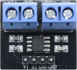
Pin Configuration and Descriptions:
The MAX471 is typically available in an 8-pin package. Below is the pinout and description:
| Pin Number | Pin Name | Description |
|---|---|---|
| 1 | V+ | Positive supply voltage |
| 2 | IN+ | Non-inverting input |
| 3 | IN- | Inverting input |
| 4 | GND | Ground |
| 5 | OUT | Output voltage proportional to sensed current |
| 6 | RS+ | Positive terminal of the sense resistor |
| 7 | RS- | Negative terminal of the sense resistor |
| 8 | V- | Negative supply voltage (optional, for dual supply) |
Usage Instructions
The MAX471 is straightforward to use in a circuit. Below are the steps and considerations for proper usage:
How to Use:
Power Supply:
- Connect the V+ pin to a positive supply voltage (3V to 36V).
- Connect the GND pin to the ground of the circuit.
- If using a dual supply, connect the V- pin to the negative supply voltage.
Input Connections:
- Connect the IN+ and IN- pins to the input signal you wish to amplify or monitor.
- Ensure the input voltage does not exceed the supply voltage range.
Current Sensing:
- Place a low-value sense resistor (e.g., 0.1Ω) between the RS+ and RS- pins.
- The voltage drop across the sense resistor will be amplified and output at the OUT pin.
Output Connection:
- Connect the OUT pin to the desired load or measurement device.
- The output voltage will be proportional to the current flowing through the sense resistor.
Important Considerations:
- Use a precision sense resistor with a low temperature coefficient for accurate current sensing.
- Decouple the power supply with a capacitor (e.g., 0.1 µF) close to the V+ pin to reduce noise.
- Avoid exceeding the maximum input voltage range to prevent damage to the component.
- For optimal performance, ensure proper PCB layout with short and low-resistance connections.
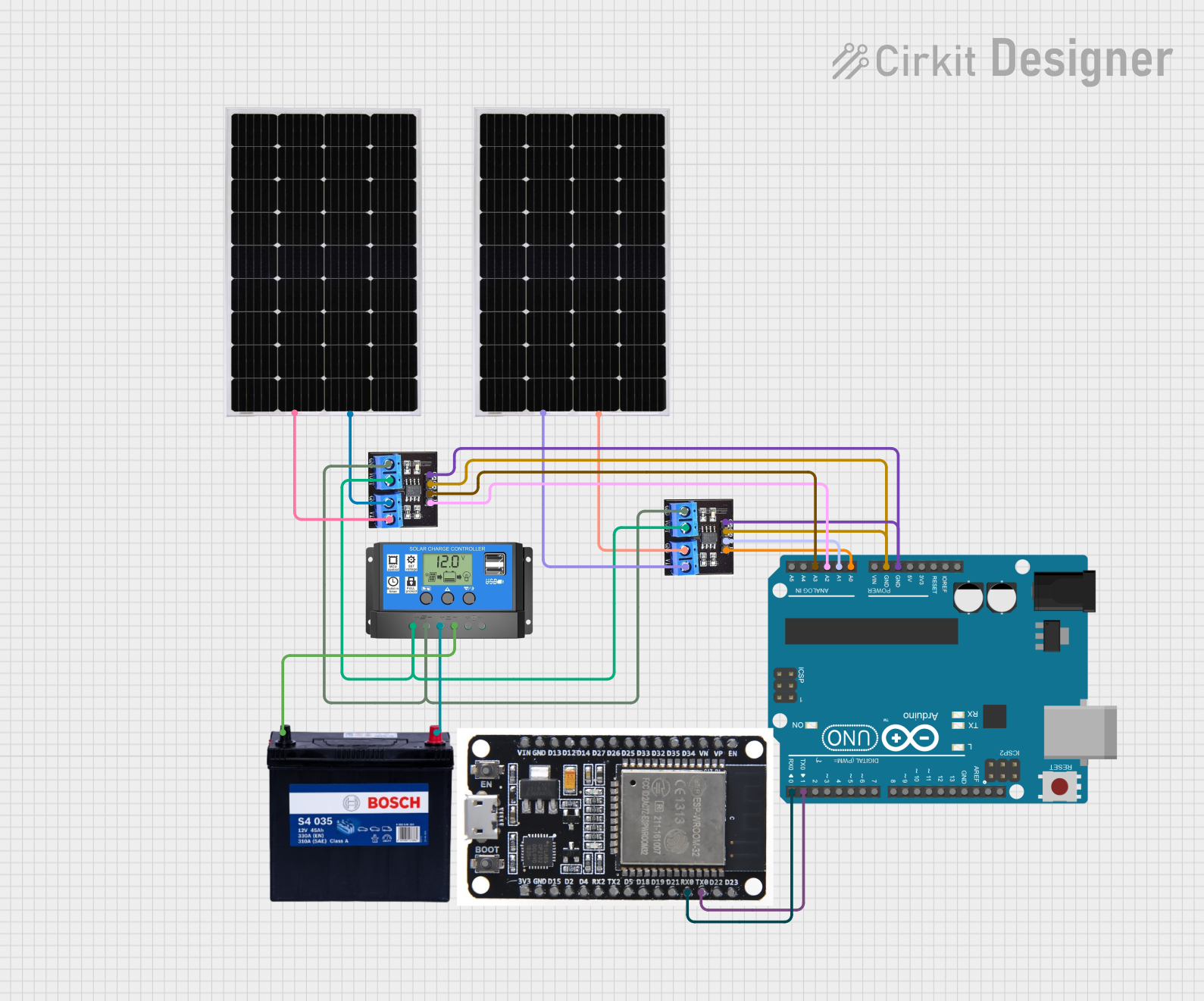
Example: Using MAX471 with Arduino UNO
The MAX471 can be used with an Arduino UNO to measure current. Below is an example circuit and code:
Circuit:
- Connect the V+ pin of the MAX471 to the 5V pin of the Arduino.
- Connect the GND pin of the MAX471 to the GND pin of the Arduino.
- Connect the OUT pin of the MAX471 to an analog input pin (e.g., A0) on the Arduino.
- Place a sense resistor (e.g., 0.1Ω) between RS+ and RS- to measure current.
Code:
// MAX471 Current Sensor Example with Arduino UNO
// Reads the output voltage from the MAX471 and calculates the current

const int sensorPin = A0; // Analog pin connected to MAX471 OUT pin
const float senseResistor = 0.1; // Value of the sense resistor in ohms
const float gain = 1.0; // Gain of the MAX471 (adjust if necessary)

void setup() {
  Serial.begin(9600); // Initialize serial communication
}

void loop() {
  int sensorValue = analogRead(sensorPin); // Read the analog value
  float voltage = (sensorValue / 1023.0) * 5.0; // Convert to voltage
  float current = voltage / (gain * senseResistor); // Calculate current

  // Print the current to the Serial Monitor
  Serial.print("Current: ");
  Serial.print(current, 3); // Print current with 3 decimal places
  Serial.println(" A");

  delay(1000); // Wait for 1 second before the next reading
}
Troubleshooting and FAQs
Common Issues:
No Output Voltage:
- Ensure the power supply is connected and within the specified range.
- Verify that the sense resistor is properly connected between RS+ and RS-.
Inaccurate Current Measurement:
- Check the value and tolerance of the sense resistor.
- Ensure the input voltage does not exceed the specified range.
Excessive Noise in Output:
- Add a decoupling capacitor (e.g., 0.1 µF) near the V+ pin.
- Use proper grounding techniques to minimize noise.
FAQs:
Q: Can the MAX471 be used for AC current sensing?
A: Yes, the MAX471 can sense AC current, but the output will be a rectified signal proportional to the current. Additional circuitry may be required to process the AC signal.
Q: What is the maximum current the MAX471 can measure?
A: The maximum measurable current depends on the value of the sense resistor and the supply voltage. Ensure the voltage drop across the sense resistor does not exceed the input voltage range.
Q: Can I use the MAX471 with a 3.3V microcontroller?
A: Yes, the MAX471 can operate with a 3.3V supply. Ensure the output voltage is within the input range of the microcontroller's ADC.
By following the guidelines and best practices outlined in this documentation, you can effectively use the MAX471 in your projects for accurate current sensing and signal amplification.