How to Use BQ25606: Examples, Pinouts, and Specs
Introduction
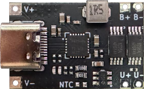
The BQ25606 is a highly integrated Li-Ion and Li-Polymer battery charger IC designed by Texas Instruments. It features a built-in power path management system, allowing seamless operation of the device while charging the battery. The component supports input voltages up to 28V and offers a programmable charge current, making it ideal for portable devices, battery-powered systems, and other energy management applications.
Explore Projects Built with BQ25606

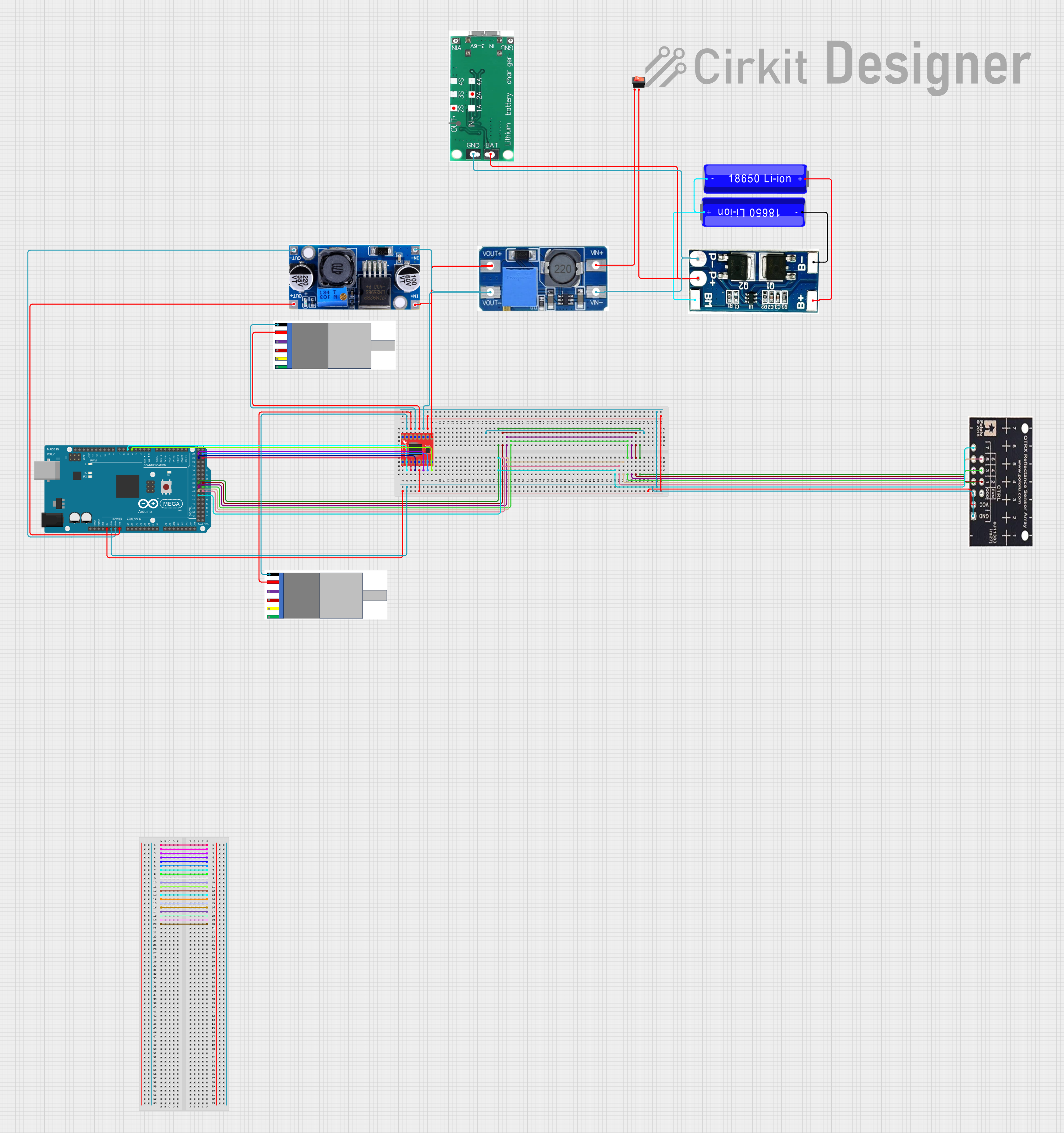

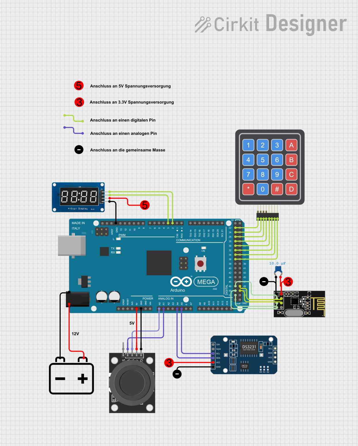
Explore Projects Built with BQ25606
Common Applications
- Smartphones and tablets
- Wearable devices
- Power banks
- Portable medical equipment
- Battery management systems
Technical Specifications
Key Technical Details
| Parameter | Value |
|---|---|
| Input Voltage Range | 3.9V to 28V |
| Operating Input Voltage | 3.9V to 14V |
| Battery Regulation Voltage | 4.2V (default, programmable) |
| Charge Current Range | Up to 3A (programmable) |
| Input Current Limit | Programmable up to 3.25A |
| Power Path Management | Integrated |
| Efficiency | Up to 92% |
| Package Type | 24-pin WQFN (4mm x 4mm) |
| Operating Temperature | -40°C to 125°C |
Pin Configuration and Descriptions
The BQ25606 is available in a 24-pin WQFN package. Below is the pin configuration and description:
| Pin Number | Pin Name | Description |
|---|---|---|
| 1 | PMID | Power path output for system load |
| 2 | SYS | System output voltage |
| 3 | BAT | Battery connection |
| 4 | TS | Temperature sense input for battery pack |
| 5 | ILIM | Input current limit programming pin |
| 6 | ISET | Charge current programming pin |
| 7 | STAT | Charging status indicator |
| 8 | CE | Charge enable input (active low) |
| 9 | OTG | Boost mode enable input |
| 10 | SDA | I2C data line |
| 11 | SCL | I2C clock line |
| 12 | VBUS | Input power supply |
| 13 | GND | Ground |
| 14 | REGN | Internal regulator output |
| 15 | D+/D- | USB D+/D- data lines for input current limit detection |
| 16 | PG | Power good indicator |
| 17 | VREF | Reference voltage output |
| 18 | OTG_VBUS | Boost mode output |
| 19-24 | NC | No connection |
Usage Instructions
How to Use the BQ25606 in a Circuit
- Power Supply Connection: Connect the input power supply (VBUS) to a voltage source within the range of 3.9V to 28V. Ensure the input voltage does not exceed the maximum rating.
- Battery Connection: Connect the battery to the BAT pin. The BQ25606 supports single-cell Li-Ion or Li-Polymer batteries.
- Programming Charge Current: Use a resistor on the ISET pin to set the desired charge current. Refer to the datasheet for the resistor-to-current mapping.
- Input Current Limit: Use a resistor on the ILIM pin to program the input current limit.
- Temperature Monitoring: Connect a thermistor to the TS pin for battery temperature monitoring.
- Status Indicators: Use the STAT and PG pins to monitor charging status and power good conditions.
- I2C Communication: If needed, connect the SDA and SCL pins to a microcontroller for advanced configuration and monitoring.
Important Considerations and Best Practices
- Thermal Management: Ensure proper PCB layout and thermal dissipation to prevent overheating, especially at high charge currents.
- Input Voltage Protection: Use an external TVS diode or similar protection to safeguard the IC from voltage spikes above 28V.
- Battery Safety: Always use a battery with a built-in protection circuit to prevent overcharging or deep discharge.
- Decoupling Capacitors: Place appropriate decoupling capacitors near the VBUS, SYS, and BAT pins to ensure stable operation.
Example: Using BQ25606 with Arduino UNO
The BQ25606 can be controlled via I2C using an Arduino UNO. Below is an example code snippet to read the charging status:
#include <Wire.h>

#define BQ25606_I2C_ADDRESS 0x6B // Default I2C address for BQ25606

void setup() {
  Wire.begin(); // Initialize I2C communication
  Serial.begin(9600); // Initialize serial communication for debugging
}

void loop() {
  Wire.beginTransmission(BQ25606_I2C_ADDRESS);
  Wire.write(0x0B); // Address of the status register
  Wire.endTransmission(false); // Send the address, keep the connection open

  Wire.requestFrom(BQ25606_I2C_ADDRESS, 1); // Request 1 byte from the status register
  if (Wire.available()) {
    byte status = Wire.read(); // Read the status byte
    Serial.print("Charging Status: ");
    if (status & 0x08) {
      Serial.println("Charging in Progress");
    } else if (status & 0x10) {
      Serial.println("Charge Complete");
    } else {
      Serial.println("Not Charging");
    }
  }
  delay(1000); // Wait 1 second before reading again
}
Notes:
- Ensure the I2C pull-up resistors are properly connected.
- Modify the I2C address if the default address is changed.
Troubleshooting and FAQs
Common Issues and Solutions
Device Overheating
- Cause: High charge current or insufficient thermal dissipation.
- Solution: Reduce the charge current or improve PCB thermal design.
Battery Not Charging
- Cause: Incorrect resistor values on ISET or ILIM pins.
- Solution: Verify resistor values and ensure they match the desired current settings.
No Output on SYS Pin
- Cause: Input power not connected or insufficient.
- Solution: Check the VBUS voltage and ensure it is within the operating range.
I2C Communication Fails
- Cause: Incorrect wiring or I2C address mismatch.
- Solution: Verify SDA/SCL connections and ensure the correct I2C address is used.
FAQs
Can the BQ25606 charge a 2-cell battery?
- No, the BQ25606 is designed for single-cell Li-Ion or Li-Polymer batteries only.
What happens if the input voltage exceeds 28V?
- The device may be damaged. Use external protection, such as a TVS diode, to prevent overvoltage.
Is the charge current adjustable during operation?
- Yes, the charge current can be dynamically adjusted by changing the resistor on the ISET pin or via I2C.
Can the BQ25606 operate without a battery connected?
- Yes, the power path management feature allows the system to operate directly from the input power supply.
By following this documentation, users can effectively integrate the BQ25606 into their designs and troubleshoot common issues.