How to Use verter_pad: Examples, Pinouts, and Specs
Introduction
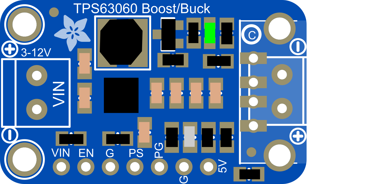
The Verter_Pad is an innovative electronic component designed to convert DC power from a power source into a regulated and adjustable voltage output. This versatile device is essential for providing a stable power supply to electronic circuits, especially when the input voltage is not aligned with the voltage requirements of the components in the circuit. Common applications include battery-powered projects, portable devices, and any system that requires a specific voltage level for operation.
Explore Projects Built with verter_pad
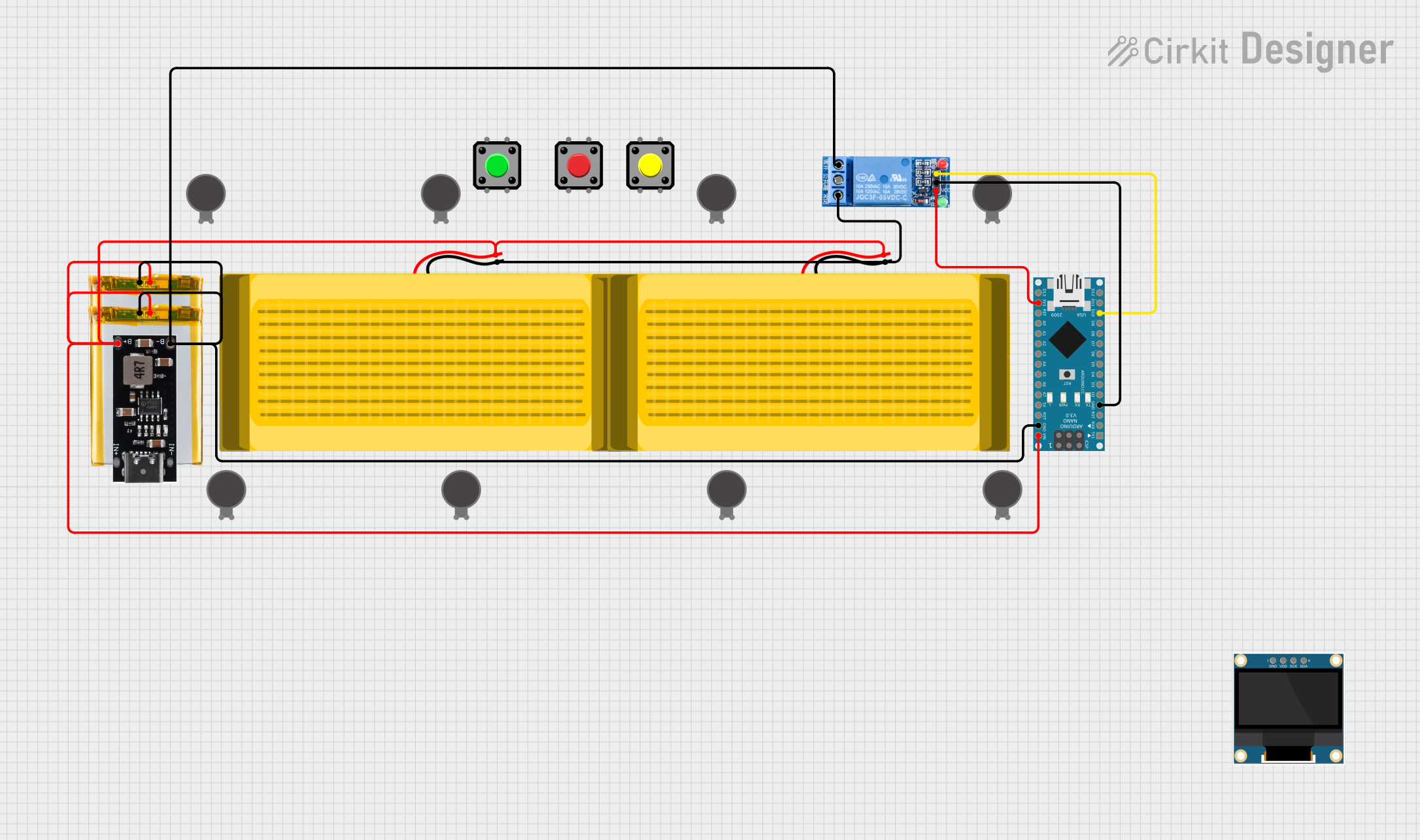
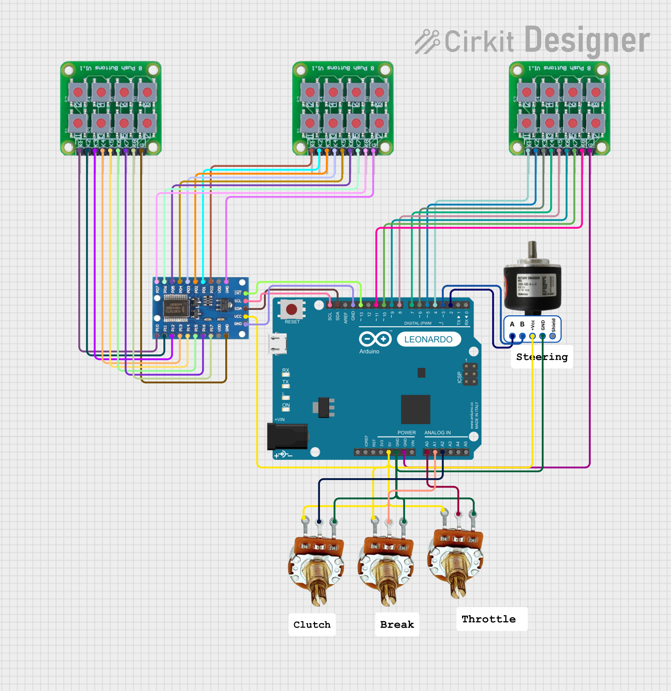

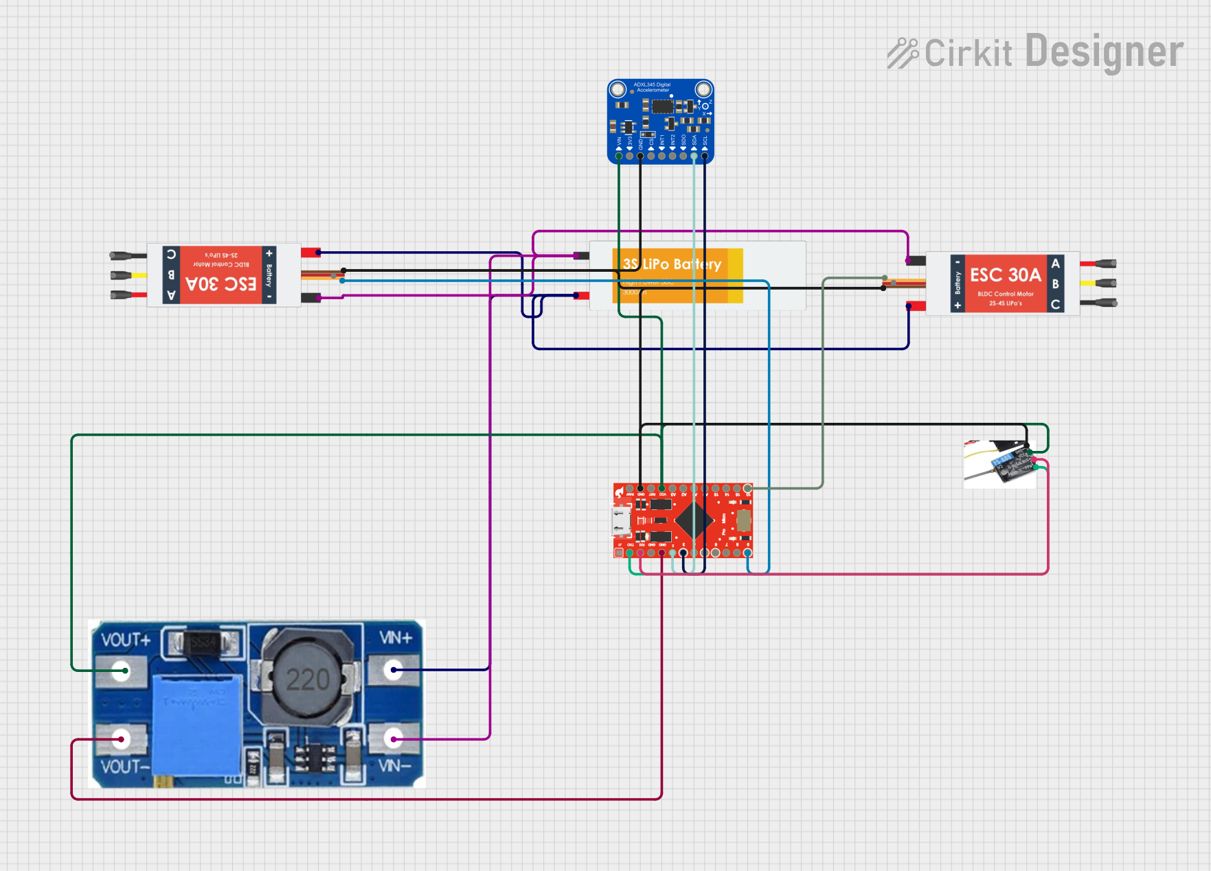
Explore Projects Built with verter_pad
Technical Specifications
Key Technical Details
- Input Voltage Range: 2V to 5.5V
- Output Voltage Range: 1.8V to 5V (adjustable)
- Maximum Output Current: 500mA
- Conversion Efficiency: Up to 95%
- Operating Temperature: -40°C to +85°C
- Quiescent Current: 0.1mA
Pin Configuration and Descriptions
| Pin Number | Name | Description |
|---|---|---|
| 1 | VIN | Input voltage to the Verter_Pad. Connect to your DC power source. |
| 2 | GND | Ground pin. Connect to the ground of your power source and circuit. |
| 3 | VOUT | Regulated output voltage. Connect to the power input of your circuit. |
| 4 | ADJ | Adjustment pin. Connect to a resistor or potentiometer to set VOUT. |
Usage Instructions
How to Use the Verter_Pad in a Circuit
Connecting Power Source:
- Connect the positive terminal of your DC power source to the VIN pin.
- Connect the negative terminal to the GND pin.
Adjusting Output Voltage:
- Connect a resistor or potentiometer between the ADJ and GND pins.
- Adjust the resistance to change the output voltage according to the desired level.
Connecting to Load:
- Connect the VOUT pin to the power input of your electronic circuit.
- Ensure that the adjusted output voltage matches the voltage requirements of your circuit.
Important Considerations and Best Practices
- Always verify the input voltage range before connecting the Verter_Pad to avoid damage.
- Do not exceed the maximum output current rating.
- Use a multimeter to confirm the output voltage before connecting to sensitive components.
- If using a potentiometer for voltage adjustment, choose one with a high resolution for precise control.
- Ensure proper heat dissipation if the Verter_Pad is expected to handle high power levels.
Troubleshooting and FAQs
Common Issues and Solutions
- Output Voltage is Too Low or Too High:
- Check the resistance between the ADJ and GND pins. Adjust the resistor or potentiometer to correct the voltage.
- Verter_Pad is Overheating:
- Ensure that the current draw is within the specified limits.
- Improve ventilation or add a heatsink to the Verter_Pad.
FAQs
- Q: Can I use the Verter_Pad with a 9V battery?
- A: No, the input voltage range is 2V to 5.5V. Exceeding this range can damage the component.
- Q: How do I set a specific output voltage?
- A: Use the formula provided in the datasheet to calculate the resistance needed for your desired output voltage, and adjust the resistor or potentiometer accordingly.
Example Code for Arduino UNO
// Example code to read the output voltage of the Verter_Pad using an Arduino UNO

const int analogPin = A0; // Connect VOUT of Verter_Pad to A0 of Arduino

void setup() {
  Serial.begin(9600);
}

void loop() {
  int sensorValue = analogRead(analogPin); // Read the analog value from Verter_Pad
  float voltage = sensorValue * (5.0 / 1023.0); // Convert to voltage
  Serial.print("Output Voltage: ");
  Serial.println(voltage);
  delay(1000); // Wait for a second before reading again
}
Remember to adjust the Verter_Pad to output a voltage within the range that the Arduino can handle on its analog inputs (0-5V). The code above assumes that the Verter_Pad's output voltage is within this range.