How to Use Adafruit Precision RTC FeatherWing: Examples, Pinouts, and Specs
Introduction
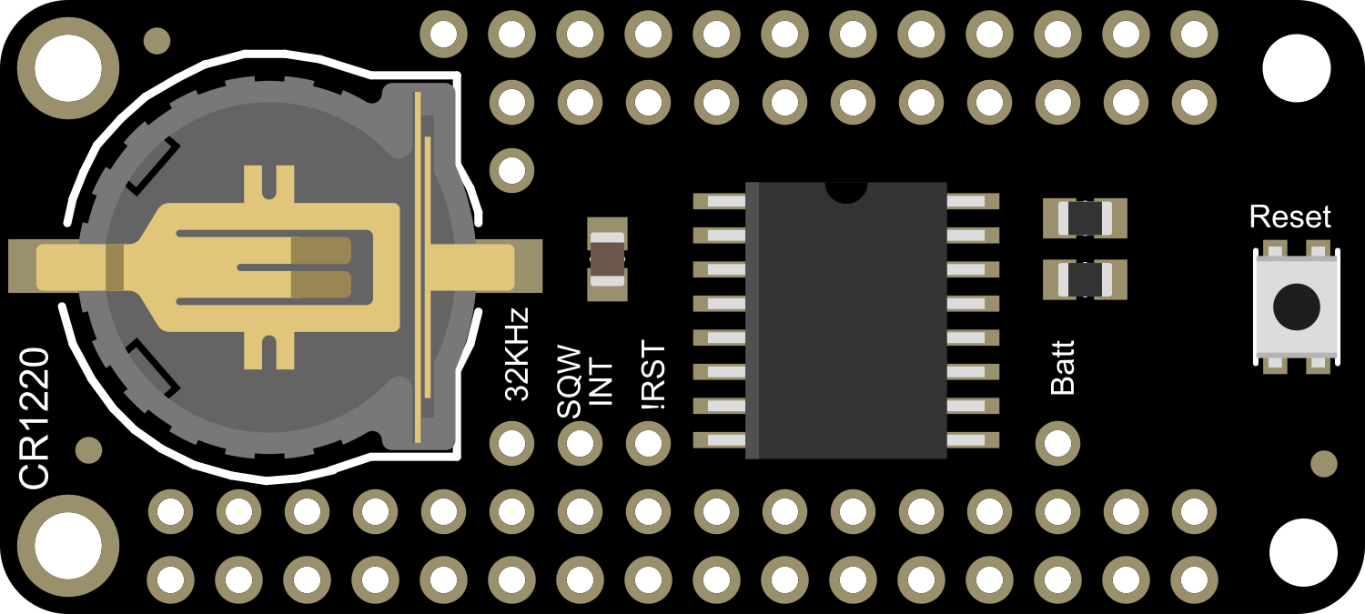
The Adafruit Precision RTC FeatherWing is an essential electronic component for projects requiring accurate timekeeping. It utilizes the high-precision DS3231 Real-Time Clock (RTC) chip, which maintains seconds, minutes, hours, day, date, month, and year information with a built-in temperature-compensated crystal oscillator (TCXO) and crystal. The module is designed to be stackable and easily integrates with the Feather ecosystem of development boards, making it ideal for applications such as data logging, clocks, timers, and alarms.
Explore Projects Built with Adafruit Precision RTC FeatherWing


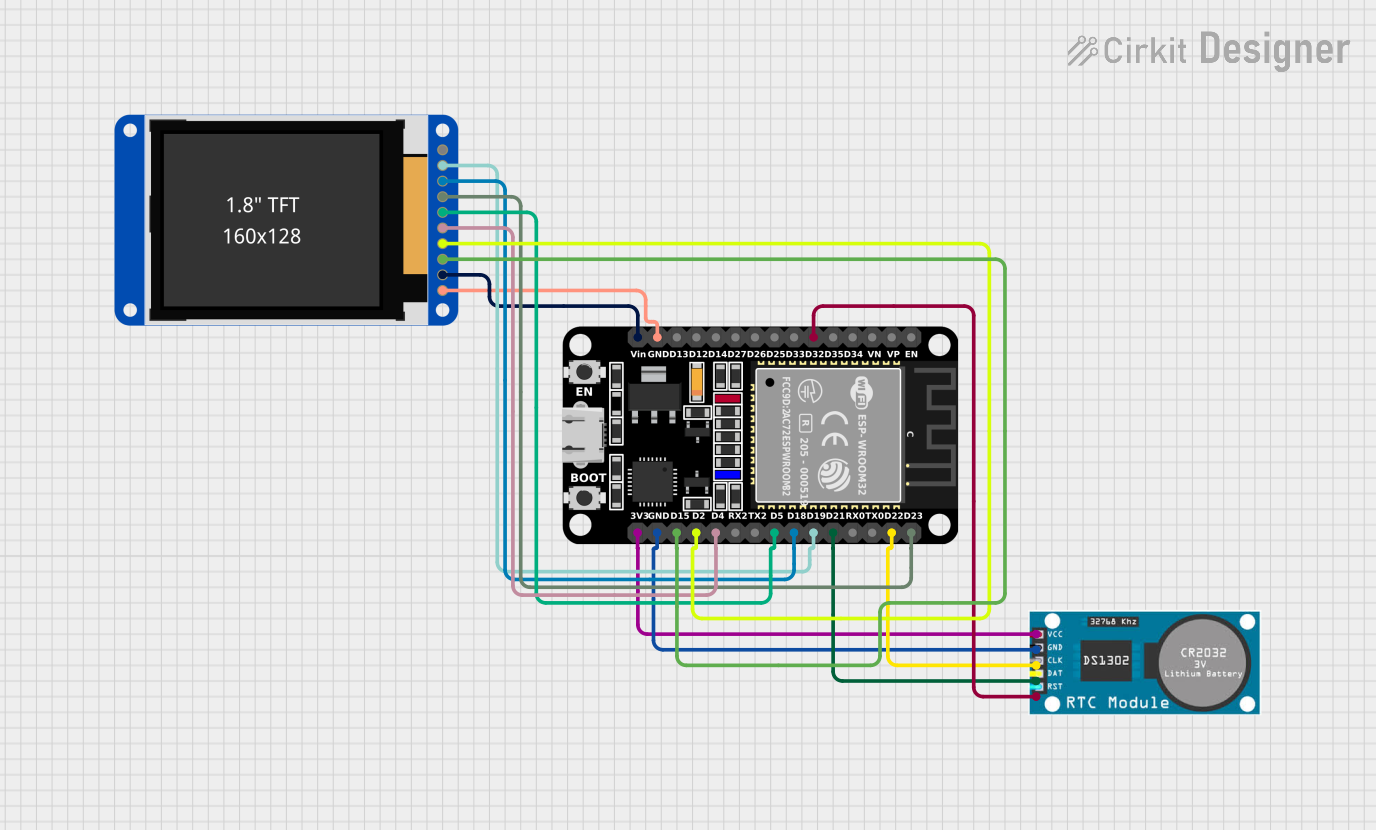
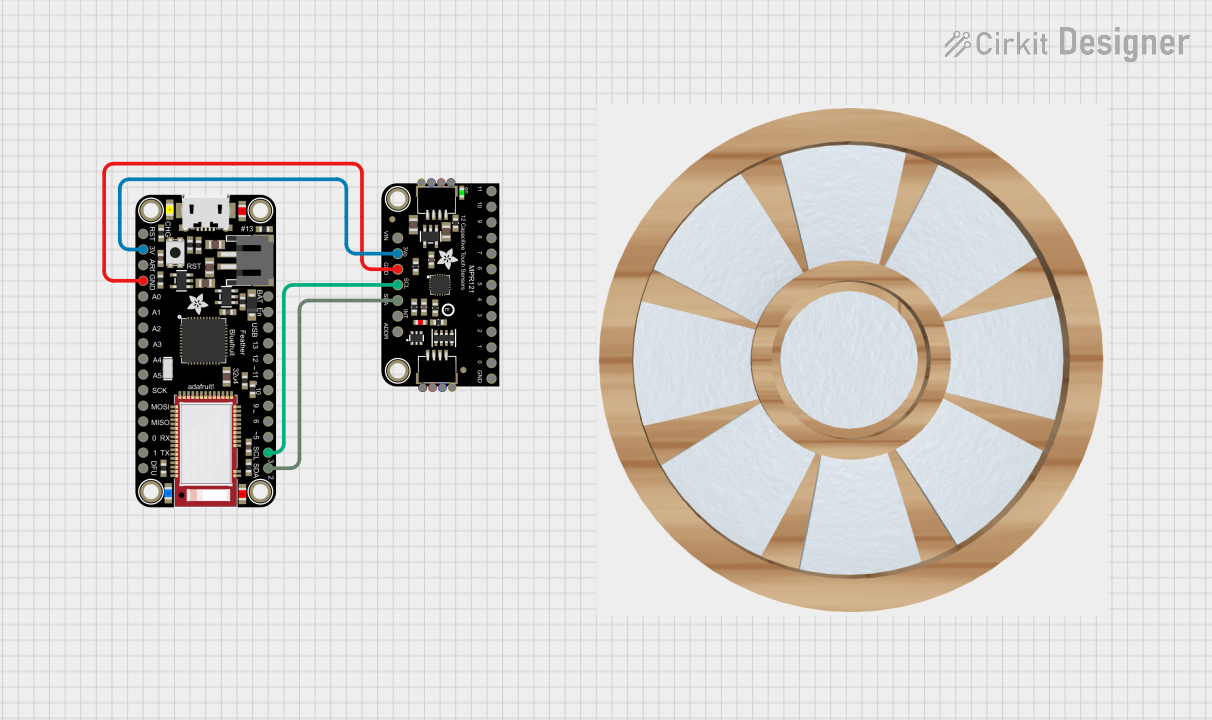
Explore Projects Built with Adafruit Precision RTC FeatherWing
Common Applications and Use Cases
- Time-sensitive applications
- Data logging with time stamps
- Clocks and watches
- Scheduled automation (e.g., turning on/off lights)
- Wearable electronics
Technical Specifications
Key Technical Details
- Voltage: 3.3V to 5V power and logic
- Current: 2mA (typical)
- Time Accuracy: ±2ppm from 0°C to +40°C
- Battery Backup: Yes (CR1220 coin cell not included)
- Interface: I2C
- I2C Address: 0x68 (default)
Pin Configuration and Descriptions
| Pin | Description |
|---|---|
| GND | Ground connection |
| 3V | 3.3V power supply |
| SCL | I2C clock signal |
| SDA | I2C data signal |
| RST | Reset pin (optional use) |
| SQW | Square wave output (configurable) |
| 32K | 32.768 kHz output (for external use) |
Usage Instructions
Integrating with a Circuit
- Powering the Module: Connect the 3V pin to a 3.3V supply from your Feather board, and the GND pin to ground.
- I2C Communication: Connect SCL and SDA to the corresponding I2C pins on your Feather board.
- Battery Backup: Insert a CR1220 coin cell battery into the holder to maintain timekeeping during power loss.
Important Considerations and Best Practices
- Ensure that the I2C address of the RTC does not conflict with other I2C devices in your circuit.
- The SQW pin can be used for generating square wave signals; configure it according to your needs.
- The 32K pin outputs a precise 32.768 kHz signal that can be used to drive timers or other devices.
- Always insert the battery in the correct orientation to avoid damage to the RTC or the battery.
Example Code for Arduino UNO
#include <Wire.h>
#include <RTClib.h>

RTC_DS3231 rtc;

void setup() {
  Serial.begin(9600);

  // Check if the RTC is connected correctly
  if (!rtc.begin()) {
    Serial.println("Couldn't find RTC");
    while (1);
  }

  // Check if the RTC lost power and if so, set the time
  if (rtc.lostPower()) {
    Serial.println("RTC lost power, setting the time!");
    // The following line sets the RTC to the date & time this sketch was compiled
    rtc.adjust(DateTime(F(__DATE__), F(__TIME__)));
  }
}

void loop() {
  DateTime now = rtc.now();

  // Print the current date and time
  Serial.print(now.year(), DEC);
  Serial.print('/');
  Serial.print(now.month(), DEC);
  Serial.print('/');
  Serial.print(now.day(), DEC);
  Serial.print(" ");
  Serial.print(now.hour(), DEC);
  Serial.print(':');
  Serial.print(now.minute(), DEC);
  Serial.print(':');
  Serial.print(now.second(), DEC);
  Serial.println();

  // Wait for a second
  delay(1000);
}
Troubleshooting and FAQs
Common Issues
- Time not accurate: Ensure the coin cell battery is inserted and charged. Check for proper I2C communication.
- Module not recognized: Verify connections and I2C address. Ensure no other device is using the same I2C address.
- No square wave output: Confirm that the SQW pin is configured correctly in your code.
Solutions and Tips for Troubleshooting
- Double-check wiring, especially the I2C lines and power connections.
- Use I2C scanner code to confirm the RTC module's address.
- Replace the coin cell battery if the RTC has lost power or time is not maintained during power cycles.
FAQs
Q: Can I use this module with a 5V system? A: Yes, the module is 5V compliant for power and logic levels.
Q: How long will the RTC keep time with the battery backup? A: With a fresh CR1220 coin cell battery, the RTC can keep time for several years.
Q: Is it necessary to use the reset pin? A: No, the RST pin is optional and is typically not required for normal operation.
Q: Can I set alarms with this RTC? A: Yes, the DS3231 chip supports two programmable time-of-day alarms.
Q: How do I set the time on the RTC?
A: You can set the time using the rtc.adjust(DateTime(__DATE__, __TIME__)); function in your setup code, as shown in the example above. This sets the RTC to the time when the sketch was compiled.