How to Use LCD TFT, ST7735S: Examples, Pinouts, and Specs
Introduction
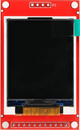
The LCD TFT, ST7735S, is a compact, full-color display module designed for use in embedded systems and microcontroller-based projects. Manufactured by Arduino, this module is compatible with the Arduino UNO and other microcontrollers, making it an excellent choice for projects requiring a graphical user interface. The ST7735S driver IC powers the display, offering a resolution of 128x160 pixels with 18-bit color depth, enabling vibrant and detailed visuals.
Explore Projects Built with LCD TFT, ST7735S


Explore Projects Built with LCD TFT, ST7735S
Common Applications and Use Cases
- Graphical user interfaces for embedded systems
- Real-time data visualization (e.g., temperature, sensor readings)
- Gaming projects and animations
- Portable devices and wearables
- Educational and prototyping purposes
Technical Specifications
Key Technical Details
| Parameter | Specification |
|---|---|
| Display Type | TFT LCD |
| Driver IC | ST7735S |
| Resolution | 128x160 pixels |
| Color Depth | 18-bit (262,144 colors) |
| Operating Voltage | 3.3V |
| Interface | SPI (Serial Peripheral Interface) |
| Backlight | LED |
| Dimensions | 1.8 inches (diagonal) |
| Operating Temperature | -20°C to 70°C |
Pin Configuration and Descriptions
| Pin Name | Pin Number | Description |
|---|---|---|
| VCC | 1 | Power supply input (3.3V recommended) |
| GND | 2 | Ground connection |
| CS | 3 | Chip Select (active low) |
| RESET | 4 | Reset pin for the display |
| A0 (DC) | 5 | Data/Command control pin |
| SDA | 6 | Serial Data (MOSI for SPI communication) |
| SCK | 7 | Serial Clock (SPI clock input) |
| LED | 8 | Backlight control (connect to 3.3V or PWM pin) |
Usage Instructions
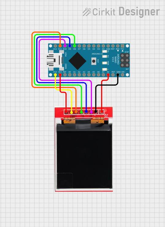
How to Use the Component in a Circuit
- Power Supply: Connect the VCC pin to a 3.3V power source and the GND pin to the ground.
- SPI Communication: Connect the SDA (MOSI) and SCK pins to the corresponding SPI pins on the Arduino UNO.
- Control Pins:
- Connect the CS pin to a digital pin on the Arduino (e.g., D10).
- Connect the RESET pin to another digital pin (e.g., D9).
- Connect the A0 (DC) pin to a digital pin (e.g., D8).
- Backlight: Connect the LED pin to 3.3V or a PWM pin for brightness control.
- Install Libraries: Use the
Adafruit_GFXandAdafruit_ST7735libraries for easy integration with Arduino.
Example Arduino Code
Below is an example code snippet to initialize and display text on the LCD TFT, ST7735S:
#include <Adafruit_GFX.h>       // Graphics library for the display
#include <Adafruit_ST7735.h>    // ST7735 driver library

// Define pin connections
#define TFT_CS     10  // Chip Select pin
#define TFT_RST    9   // Reset pin
#define TFT_DC     8   // Data/Command pin

// Initialize the display object
Adafruit_ST7735 tft = Adafruit_ST7735(TFT_CS, TFT_DC, TFT_RST);

void setup() {
  // Initialize the display
  tft.initR(INITR_BLACKTAB);  // Use the Black Tab configuration
  tft.setRotation(1);        // Set display orientation (1 = landscape)

  // Clear the screen with a black background
  tft.fillScreen(ST77XX_BLACK);

  // Set text color and size
  tft.setTextColor(ST77XX_WHITE);
  tft.setTextSize(2);

  // Display text
  tft.setCursor(10, 10);      // Set cursor position (x, y)
  tft.print("Hello, World!"); // Print text to the screen
}

void loop() {
  // No actions in the loop for this example
}
Important Considerations and Best Practices
- Voltage Levels: Ensure the display operates at 3.3V. If using a 5V microcontroller, use level shifters for the SPI pins.
- Backlight Control: Use a PWM pin to adjust the brightness of the backlight for power efficiency.
- Library Compatibility: Always use the latest versions of the
Adafruit_GFXandAdafruit_ST7735libraries for optimal performance. - Wiring: Double-check all connections to avoid damage to the display or microcontroller.
Troubleshooting and FAQs
Common Issues and Solutions
Blank Screen:
- Verify the power supply (3.3V) and ground connections.
- Ensure the SPI pins are correctly connected to the Arduino.
- Check the initialization code for correct pin assignments.
Distorted or Noisy Display:
- Ensure proper grounding between the display and the Arduino.
- Use short, high-quality wires to minimize noise in SPI communication.
Backlight Not Working:
- Confirm the LED pin is connected to 3.3V or a PWM pin.
- Check for loose or broken connections.
Library Errors:
- Ensure the
Adafruit_GFXandAdafruit_ST7735libraries are installed in the Arduino IDE. - Update the libraries to the latest version if errors persist.
- Ensure the
FAQs
Q: Can I use the display with a 5V microcontroller?
A: Yes, but you must use level shifters to convert the 5V logic signals to 3.3V for the display.
Q: How do I display images on the screen?
A: Use the Adafruit_ImageReader library to load and display BMP images from an SD card.
Q: Can I use this display with other microcontrollers?
A: Yes, the ST7735S is compatible with most microcontrollers that support SPI communication, such as ESP32, STM32, and Raspberry Pi.
Q: How do I change the screen orientation?
A: Use the setRotation() function in the code. Valid values are 0, 1, 2, and 3 for different orientations.
By following this documentation, you can effectively integrate the LCD TFT, ST7735S, into your projects and troubleshoot common issues with ease.