How to Use Tarjeta_PCB_torniquete: Examples, Pinouts, and Specs
Introduction
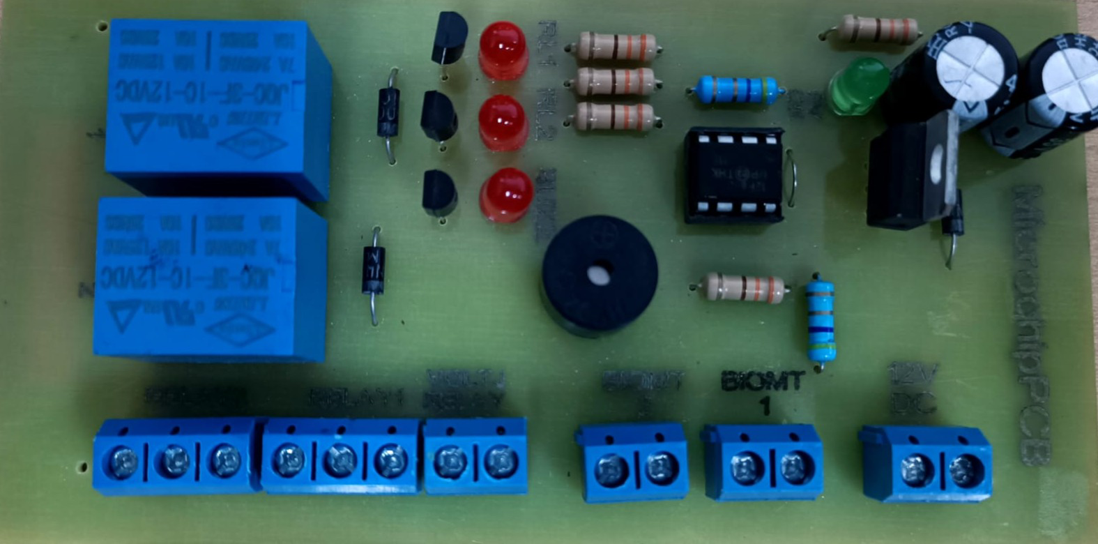
The Tarjeta_PCB_torniquete is a printed circuit board (PCB) developed by Omarsa (Part ID: 01) for controlling and managing turnstile mechanisms. This component is specifically designed for access control systems, enabling precise regulation of entry and exit in secured areas. It integrates seamlessly with various sensors, actuators, and microcontrollers, making it a versatile solution for modern access management.
Explore Projects Built with Tarjeta_PCB_torniquete
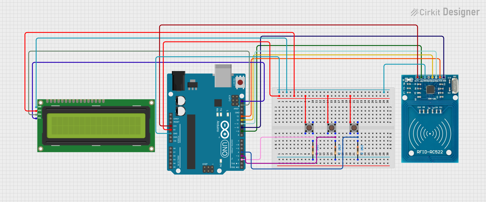
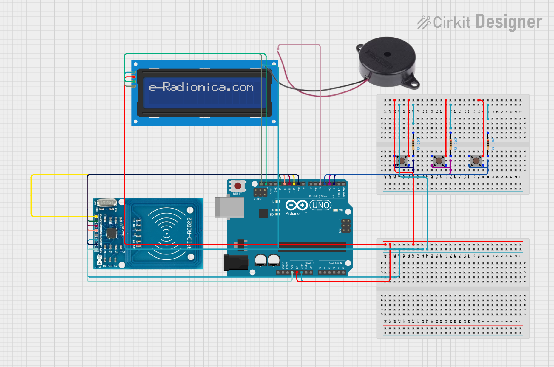
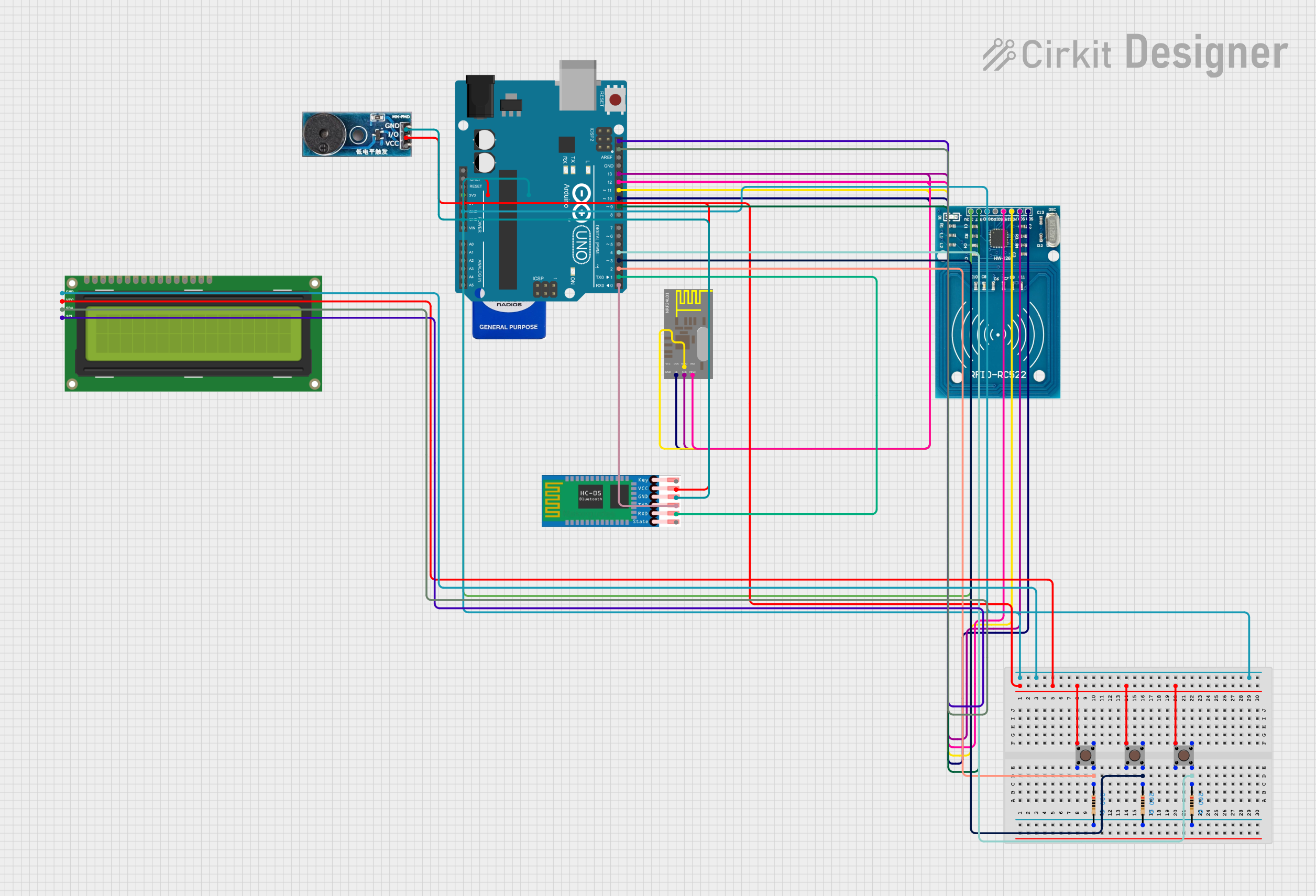
Explore Projects Built with Tarjeta_PCB_torniquete
Common Applications and Use Cases
- Access Control Systems: Used in offices, gyms, stadiums, and other secured facilities.
- Turnstile Mechanisms: Controls motorized or mechanical turnstiles for entry/exit.
- Integration with RFID or Biometric Systems: Works with authentication devices to grant or deny access.
- Event Management: Regulates crowd flow in events or public transportation hubs.
Technical Specifications
Key Technical Details
| Parameter | Value |
|---|---|
| Manufacturer | Omarsa |
| Part ID | 01 |
| Operating Voltage | 12V DC |
| Maximum Current | 2A |
| Communication Protocols | UART, I2C |
| Input Interfaces | RFID, Biometric, Push Button |
| Output Interfaces | Motor Driver, LED Indicators |
| Operating Temperature | -20°C to 70°C |
| PCB Dimensions | 100mm x 70mm |
Pin Configuration and Descriptions
| Pin Number | Pin Name | Description |
|---|---|---|
| 1 | VCC | Power input (12V DC) |
| 2 | GND | Ground connection |
| 3 | RX | UART Receive pin for communication |
| 4 | TX | UART Transmit pin for communication |
| 5 | I2C_SCL | I2C Clock line |
| 6 | I2C_SDA | I2C Data line |
| 7 | SENSOR_IN | Input for external sensors (e.g., RFID, biometric) |
| 8 | MOTOR_CTRL | Output to control the turnstile motor |
| 9 | LED_STATUS | Output for status LED indicators |
| 10 | RESET | Reset pin to restart the PCB |
Usage Instructions
How to Use the Component in a Circuit
- Power Supply: Connect the VCC pin to a 12V DC power source and the GND pin to ground.
- Communication: Use the RX and TX pins for UART communication or the I2C_SCL and I2C_SDA pins for I2C communication with a microcontroller.
- Sensor Integration: Attach external sensors (e.g., RFID readers or biometric scanners) to the SENSOR_IN pin.
- Motor Control: Connect the turnstile motor to the MOTOR_CTRL pin. Ensure the motor's voltage and current ratings are compatible.
- LED Indicators: Use the LED_STATUS pin to connect status LEDs for visual feedback.
- Reset: Use the RESET pin to restart the PCB if needed.
Important Considerations and Best Practices
- Power Supply: Ensure a stable 12V DC power source to avoid damage to the PCB.
- Sensor Compatibility: Verify that the connected sensors operate within the PCB's voltage and current limits.
- Motor Ratings: Use a motor driver circuit if the motor's current exceeds the PCB's maximum output.
- Heat Management: Operate the PCB within the specified temperature range (-20°C to 70°C) to prevent overheating.
- Secure Connections: Use proper connectors and soldering techniques to ensure reliable connections.
Example: Connecting to an Arduino UNO
The Tarjeta_PCB_torniquete can be easily interfaced with an Arduino UNO for access control applications. Below is an example code snippet for controlling the turnstile motor based on an RFID input:
#include <Wire.h> // Include I2C library for communication

#define SENSOR_IN 7    // Pin connected to SENSOR_IN on the PCB
#define MOTOR_CTRL 8   // Pin connected to MOTOR_CTRL on the PCB
#define LED_STATUS 9   // Pin connected to LED_STATUS on the PCB

void setup() {
  pinMode(SENSOR_IN, INPUT);  // Set SENSOR_IN as input
  pinMode(MOTOR_CTRL, OUTPUT); // Set MOTOR_CTRL as output
  pinMode(LED_STATUS, OUTPUT); // Set LED_STATUS as output

  Serial.begin(9600); // Initialize UART communication
  Wire.begin();       // Initialize I2C communication

  digitalWrite(MOTOR_CTRL, LOW); // Ensure motor is off at startup
  digitalWrite(LED_STATUS, LOW); // Turn off status LED at startup
}

void loop() {
  int sensorState = digitalRead(SENSOR_IN); // Read sensor input

  if (sensorState == HIGH) {
    // If sensor is triggered, activate motor and LED
    digitalWrite(MOTOR_CTRL, HIGH);
    digitalWrite(LED_STATUS, HIGH);
    delay(5000); // Keep motor active for 5 seconds
    digitalWrite(MOTOR_CTRL, LOW);
    digitalWrite(LED_STATUS, LOW);
  }

  delay(100); // Small delay to avoid rapid triggering
}
Troubleshooting and FAQs
Common Issues and Solutions
PCB Not Powering On:
- Cause: Insufficient or unstable power supply.
- Solution: Verify the power source provides a stable 12V DC and check all connections.
Motor Not Responding:
- Cause: Incorrect wiring or incompatible motor.
- Solution: Ensure the motor is properly connected to the MOTOR_CTRL pin and matches the PCB's output ratings.
No Communication with Microcontroller:
- Cause: Incorrect UART or I2C configuration.
- Solution: Double-check the baud rate for UART (default: 9600) or the I2C address.
LED Indicators Not Working:
- Cause: Faulty LED or incorrect connection.
- Solution: Test the LED separately and verify the connection to the LED_STATUS pin.
FAQs
Q: Can I use a 5V power supply instead of 12V?
A: No, the PCB requires a 12V DC power supply for proper operation.Q: Is the PCB compatible with other microcontrollers besides Arduino?
A: Yes, the PCB supports UART and I2C communication, making it compatible with most microcontrollers.Q: Can I connect multiple sensors to the PCB?
A: Yes, but you may need to use a multiplexer or additional circuitry to handle multiple inputs.Q: What happens if the PCB overheats?
A: The PCB may shut down or malfunction. Ensure proper ventilation and operate within the specified temperature range.
This documentation provides a comprehensive guide to using the Tarjeta_PCB_torniquete effectively in your projects. For further assistance, refer to the manufacturer's support resources.