How to Use 7-Segment Panel Voltmeter: Examples, Pinouts, and Specs
Introduction
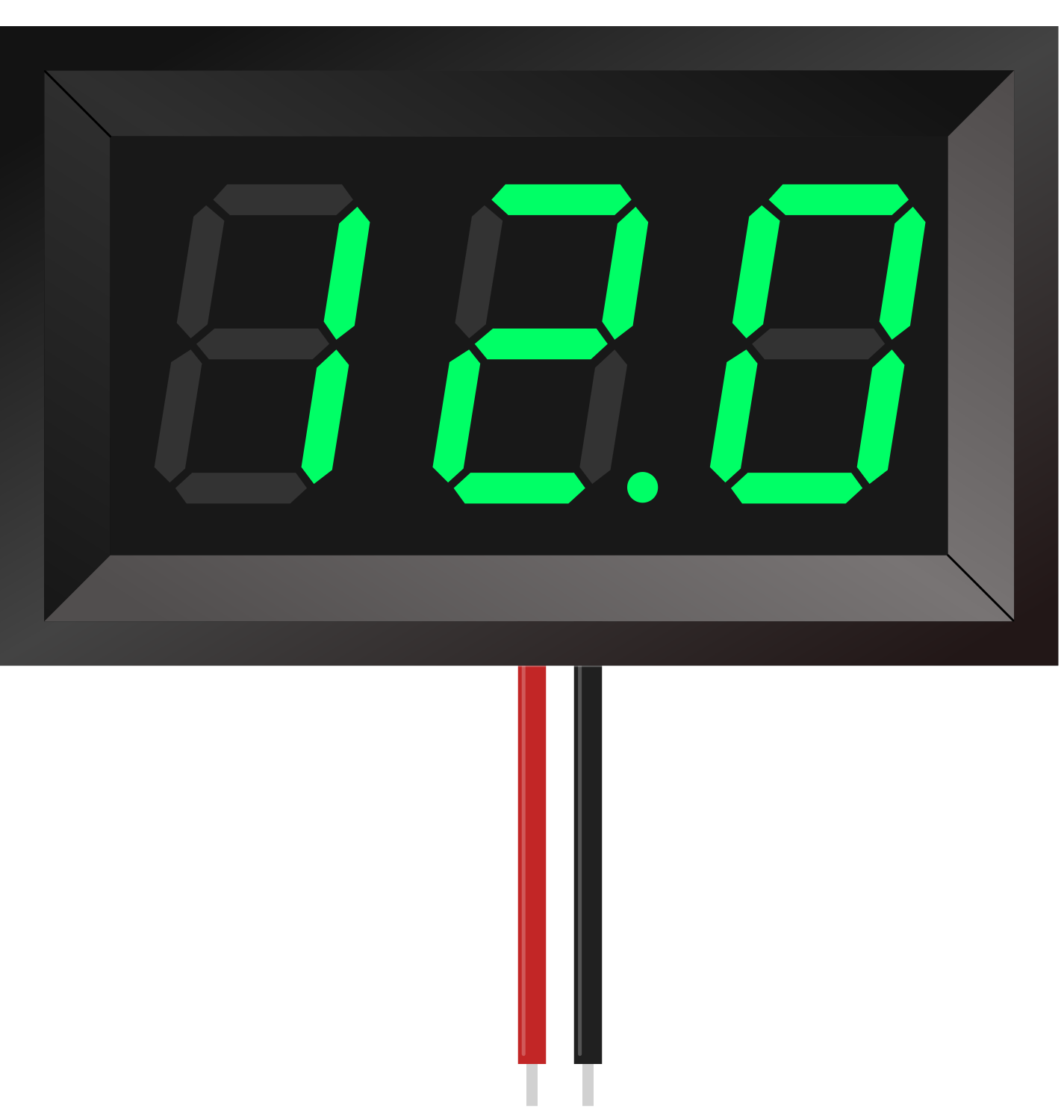
The 7-Segment Panel Voltmeter by Adafruit is a compact and efficient electronic device designed to measure and display voltage levels in a circuit. It features a bright, easy-to-read 7-segment digital display that provides real-time numerical voltage readings. This component is ideal for applications requiring precise voltage monitoring, such as power supply testing, battery monitoring, and embedded systems.
Explore Projects Built with 7-Segment Panel Voltmeter

Explore Projects Built with 7-Segment Panel Voltmeter
Common Applications and Use Cases
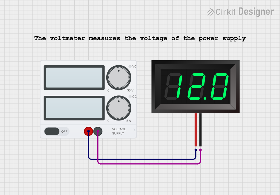
- Monitoring voltage levels in power supplies
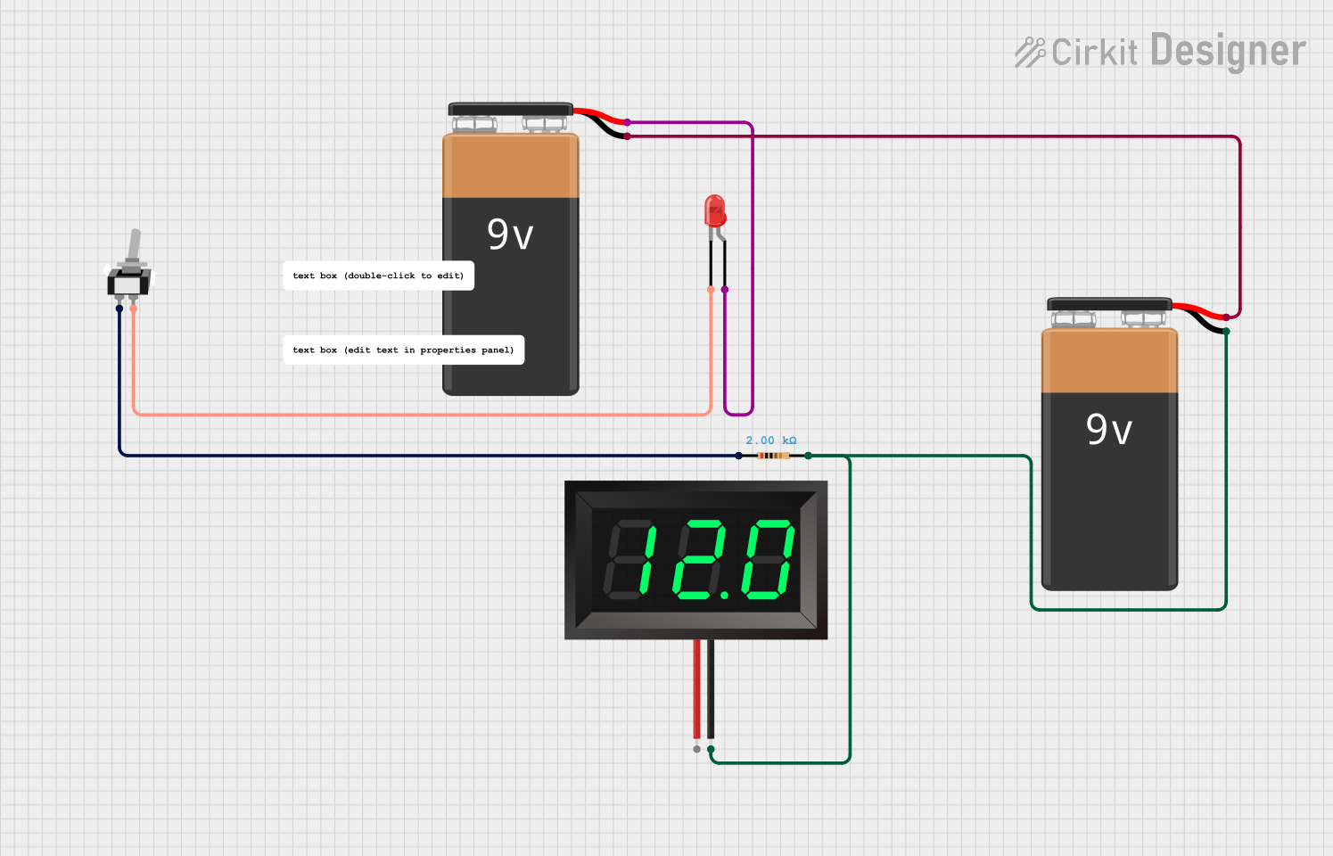
- Battery voltage measurement in portable devices
- Integration into DIY electronics projects
- Voltage display in automotive or industrial systems
- Educational tools for learning about voltage and circuits
Technical Specifications
The following table outlines the key technical details of the Adafruit 7-Segment Panel Voltmeter:
| Parameter | Specification |
|---|---|
| Operating Voltage | 4.5V to 30V DC |
| Measurement Range | 0V to 100V DC |
| Display Type | 7-segment LED (3-digit or 4-digit) |
| Display Color | Red, Green, or Blue (varies by model) |
| Input Impedance | >1MΩ |
| Accuracy | ±1% |
| Refresh Rate | ~200ms |
| Dimensions | 48mm x 29mm x 22mm |
Pin Configuration and Descriptions
The 7-Segment Panel Voltmeter typically has three connection points. The table below describes each pin:
| Pin Name | Description |
|---|---|
| V+ | Positive voltage input (connect to the measured voltage source) |
| V- | Ground connection (common ground with the circuit) |
| Power | Optional external power input (if required for operation) |
Usage Instructions
How to Use the Component in a Circuit
- Connect the Voltage Source:
- Attach the positive terminal of the voltage source to the
V+pin. - Connect the ground of the voltage source to the
V-pin.
- Attach the positive terminal of the voltage source to the
- Power the Voltmeter:
- If the measured voltage is within the operating range (4.5V to 30V), the voltmeter can self-power from the
V+andV-connections. - For lower voltages, provide an external power supply to the
Powerpin.
- If the measured voltage is within the operating range (4.5V to 30V), the voltmeter can self-power from the
- Read the Display:
- The 7-segment display will show the measured voltage in real-time.
Important Considerations and Best Practices
- Voltage Range: Ensure the input voltage does not exceed the maximum measurement range (100V DC) to avoid damage.
- Polarity: Always connect the
V+andV-pins with the correct polarity. Reversed connections can damage the device. - External Power: For voltages below 4.5V, use an external power source to ensure proper operation.
- Mounting: Secure the voltmeter in a panel or enclosure to protect it from physical damage and ensure clear visibility of the display.
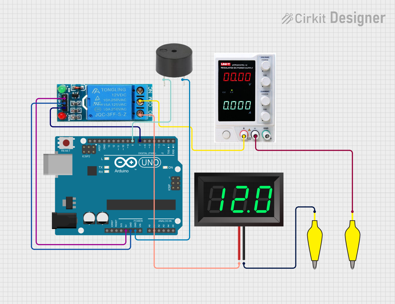
Example: Connecting to an Arduino UNO
The 7-Segment Panel Voltmeter can be used alongside an Arduino UNO to monitor voltage levels in a circuit. Below is an example of how to connect and use the voltmeter:
- Connect the
V+pin of the voltmeter to the voltage source you want to measure. - Connect the
V-pin to the Arduino's GND pin. - Optionally, use the Arduino's 5V pin to power the voltmeter if the measured voltage is below 4.5V.
Here is an example Arduino sketch to measure and display voltage using the voltmeter:
// Example Arduino code to measure voltage and display it on the serial monitor
// Note: The 7-Segment Panel Voltmeter operates independently and does not require
// direct control from the Arduino. This code is for additional voltage monitoring.

const int voltagePin = A0; // Analog pin to measure voltage
const float referenceVoltage = 5.0; // Arduino reference voltage (5V for UNO)
const float voltageDividerRatio = 2.0; // Adjust if using a voltage divider

void setup() {
  Serial.begin(9600); // Initialize serial communication
  Serial.println("Voltage Measurement Started");
}

void loop() {
  int sensorValue = analogRead(voltagePin); // Read analog input
  float voltage = (sensorValue / 1023.0) * referenceVoltage * voltageDividerRatio;

  // Print the measured voltage to the serial monitor
  Serial.print("Measured Voltage: ");
  Serial.print(voltage);
  Serial.println(" V");

  delay(500); // Wait for 500ms before the next reading
}
Note: The 7-Segment Panel Voltmeter will display the voltage independently. The Arduino code above is for additional monitoring or logging purposes.
Troubleshooting and FAQs
Common Issues and Solutions
No Display on the Voltmeter:
- Cause: Insufficient input voltage or incorrect wiring.
- Solution: Verify that the input voltage is within the operating range (4.5V to 30V) and check the wiring for proper connections.
Incorrect Voltage Reading:
- Cause: Input voltage exceeds the measurement range or poor connections.
- Solution: Ensure the input voltage is within the 0V to 100V range. Check for loose or corroded connections.
Flickering Display:
- Cause: Unstable power supply or noisy input voltage.
- Solution: Use a stable power source and add a capacitor (e.g., 10µF) across the
V+andV-pins to filter noise.
Device Overheating:
- Cause: Prolonged exposure to high input voltage.
- Solution: Ensure the input voltage does not exceed the maximum rating. Use a heat sink or cooling if necessary.
FAQs
Q1: Can the voltmeter measure AC voltage?
A1: No, the 7-Segment Panel Voltmeter is designed for DC voltage measurement only.
Q2: Can I use the voltmeter with a voltage divider?
A2: Yes, you can use a voltage divider to measure higher voltages. Ensure the divided voltage is within the voltmeter's range.
Q3: What happens if I reverse the polarity of the input voltage?
A3: Reversing the polarity can damage the voltmeter. Always double-check the connections before powering the device.
Q4: Can I use the voltmeter in outdoor environments?
A4: The voltmeter is not weatherproof. Use an appropriate enclosure to protect it from moisture and dust.
By following this documentation, you can effectively integrate the Adafruit 7-Segment Panel Voltmeter into your projects for accurate and reliable voltage measurement.