How to Use 433Mhz RF Transmitter: Examples, Pinouts, and Specs
Introduction
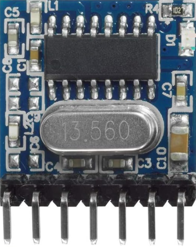
The 433MHz RF Transmitter (Manufacturer: QIACHIP, Part ID: TX118SA-4) is a compact and efficient device designed to transmit radio frequency signals at 433 MHz. It is widely used in wireless communication systems, including remote controls, wireless sensors, and Internet of Things (IoT) applications. This transmitter module is ideal for low-power, short-range communication and is often paired with a corresponding RF receiver module for bidirectional communication.
Explore Projects Built with 433Mhz RF Transmitter


Explore Projects Built with 433Mhz RF Transmitter
Common Applications
- Wireless remote controls (e.g., garage doors, home automation)
- IoT devices and smart home systems
- Wireless sensors (e.g., temperature, humidity, motion)
- Data transmission in embedded systems
- Alarm and security systems
Technical Specifications
The following table outlines the key technical details of the 433MHz RF Transmitter:
| Parameter | Value |
|---|---|
| Operating Frequency | 433 MHz |
| Operating Voltage | 3.3V - 12V |
| Operating Current | ≤ 40 mA |
| Transmission Distance | Up to 200 meters (line of sight) |
| Modulation Type | Amplitude Shift Keying (ASK) |
| Data Rate | Up to 10 kbps |
| Dimensions | 19mm x 19mm x 7mm |
Pin Configuration and Descriptions
The 433MHz RF Transmitter module has four pins, as described in the table below:
| Pin | Name | Description |
|---|---|---|
| 1 | VCC | Power supply input (3.3V to 12V). Connect to the positive terminal of the power source. |
| 2 | DATA | Data input pin. Connect to the microcontroller or data source. |
| 3 | GND | Ground pin. Connect to the ground of the power source. |
| 4 | ANT | Antenna pin. Connect to a 17.3 cm wire or a suitable 433 MHz antenna for optimal performance. |
Usage Instructions
How to Use the Component in a Circuit
- Power Supply: Connect the VCC pin to a power source (3.3V to 12V) and the GND pin to the ground.
- Data Input: Connect the DATA pin to the microcontroller's digital output pin or any data source capable of generating a digital signal.
- Antenna: Attach a 17.3 cm wire or a pre-made 433 MHz antenna to the ANT pin to ensure proper signal transmission.
- Pairing with Receiver: Use a compatible 433 MHz RF receiver module to receive the transmitted signals.
Important Considerations and Best Practices
- Power Supply: Ensure a stable power supply to avoid signal distortion or reduced range.
- Antenna Placement: Place the antenna in an open area, away from metal objects or interference sources, to maximize transmission range.
- Data Encoding: Use a suitable encoding protocol (e.g., Manchester encoding) to ensure reliable data transmission.
- Legal Compliance: Verify compliance with local regulations for RF transmission in the 433 MHz band.
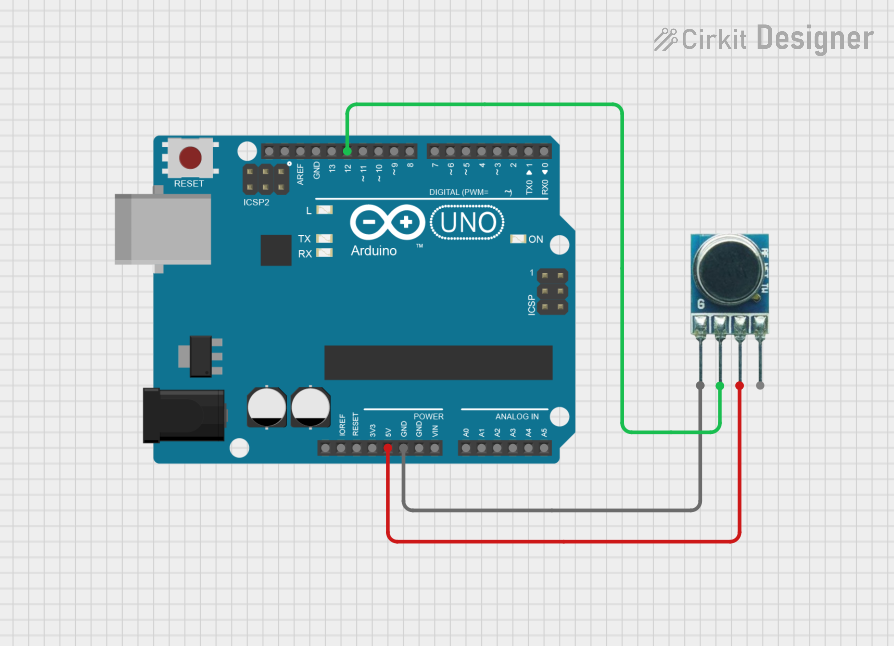
Example: Using with Arduino UNO
Below is an example of how to use the 433MHz RF Transmitter with an Arduino UNO to send a simple signal:
/*
  Example: Sending a signal using the 433MHz RF Transmitter (TX118SA-4)
  Manufacturer: QIACHIP
  Ensure the transmitter's DATA pin is connected to Arduino pin 12.
*/

#include <VirtualWire.h> // Include the VirtualWire library for RF communication

void setup() {
  vw_setup(2000); // Initialize VirtualWire at 2000 bps
  vw_set_tx_pin(12); // Set the transmitter DATA pin to Arduino pin 12
}

void loop() {
  const char *msg = "Hello, RF!"; // Message to send
  vw_send((uint8_t *)msg, strlen(msg)); // Send the message
  vw_wait_tx(); // Wait for the transmission to complete
  delay(1000); // Wait 1 second before sending the next message
}
Note: The VirtualWire library must be installed in your Arduino IDE. You can install it via the Library Manager or download it from the Arduino community.
Troubleshooting and FAQs
Common Issues and Solutions
No Signal Transmission
- Solution: Verify the power supply voltage and connections. Ensure the antenna is properly connected and placed in an open area.
Reduced Transmission Range
- Solution: Check for interference from nearby electronic devices. Use a longer or higher-quality antenna for better performance.
Data Corruption
- Solution: Implement error-checking mechanisms in your code. Use a reliable encoding protocol like Manchester encoding.
Interference with Other Devices
- Solution: Ensure the transmitter is operating within the legal frequency range and power limits for your region.
FAQs
Can I use this module with a 5V microcontroller?
- Yes, the module is compatible with 5V microcontrollers like Arduino UNO. Ensure the power supply voltage is within the 3.3V to 12V range.
What is the maximum range of this transmitter?
- The maximum range is up to 200 meters in line-of-sight conditions. Obstacles and interference may reduce the range.
Do I need an external library to use this module with Arduino?
- Yes, the
VirtualWirelibrary is commonly used for RF communication with this module.
- Yes, the
Can I use this module for bidirectional communication?
- No, this module is a transmitter only. For bidirectional communication, pair it with a 433 MHz RF receiver module.
By following this documentation, you can effectively integrate the 433MHz RF Transmitter (TX118SA-4) into your projects for reliable wireless communication.