How to Use i2c hub: Examples, Pinouts, and Specs
Introduction
An I2C hub is a device that facilitates the connection of multiple I2C devices to a single I2C bus. It enables communication between a master device (e.g., a microcontroller) and multiple slave devices while addressing challenges such as address conflicts and maintaining signal integrity. I2C hubs are particularly useful in complex systems where multiple sensors, displays, or other peripherals need to share the same I2C bus.
Explore Projects Built with i2c hub
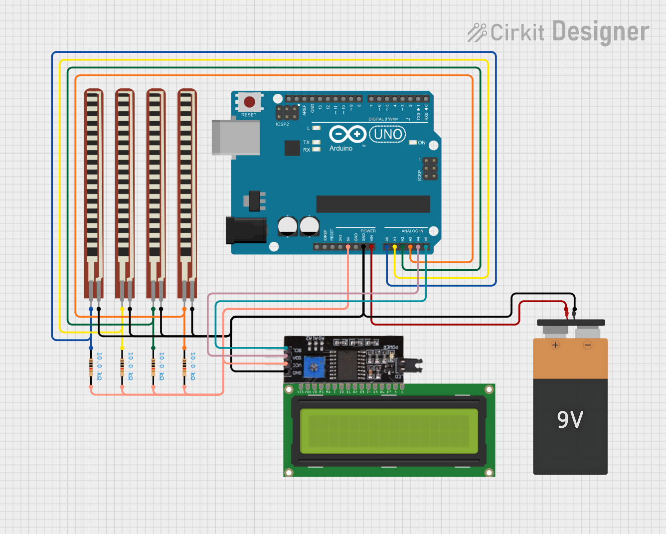
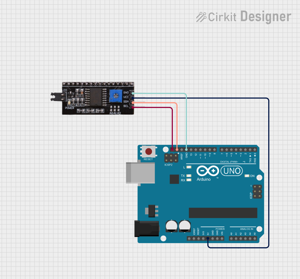

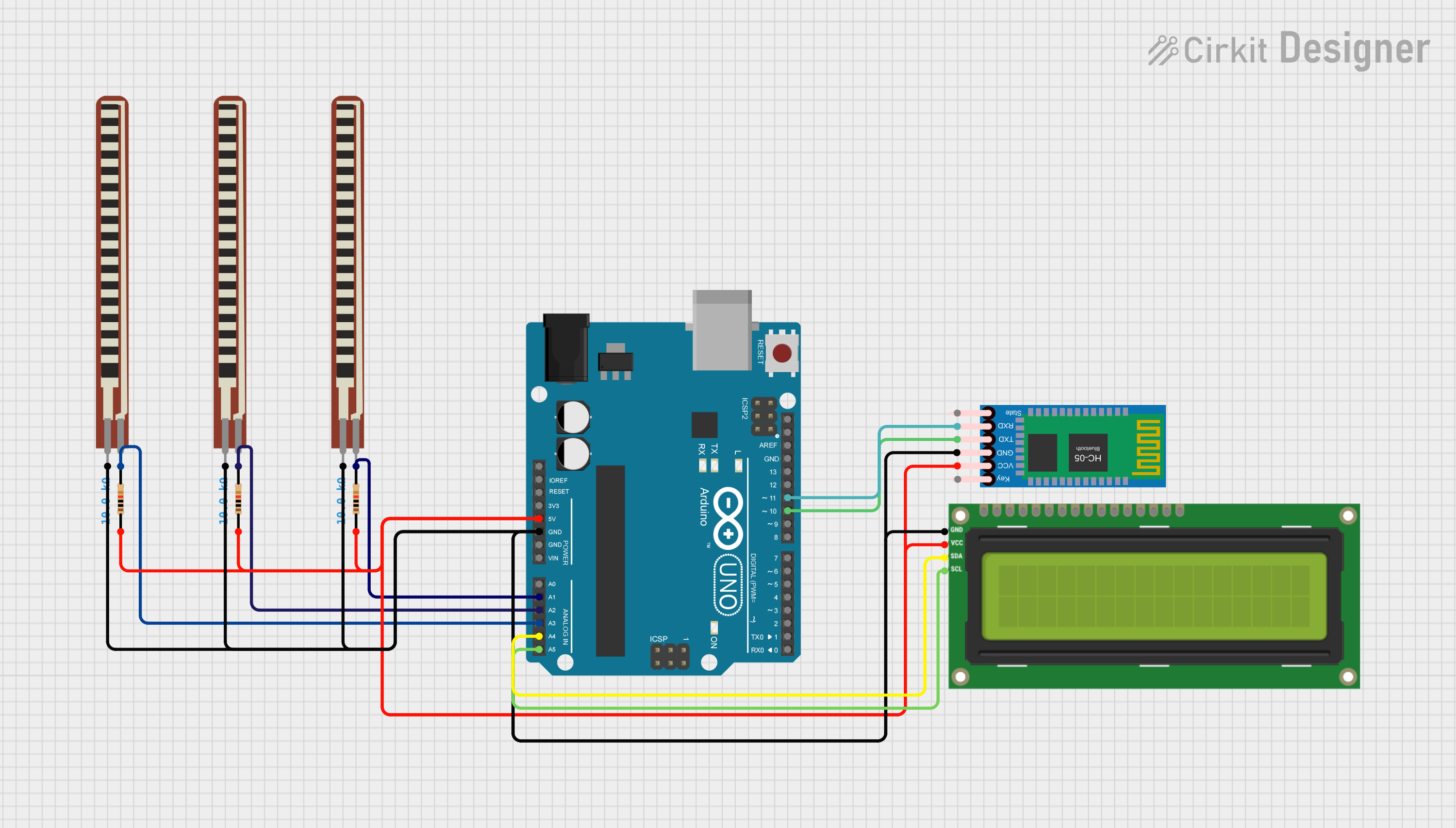
Explore Projects Built with i2c hub
Common Applications and Use Cases
- Expanding the number of I2C devices in a system.
- Resolving address conflicts by isolating devices on separate channels.
- Improving signal integrity in systems with long I2C bus lines.
- Applications in robotics, IoT devices, and industrial automation.
- Connecting multiple sensors, displays, or actuators to a single microcontroller.
Technical Specifications
Below are the general technical specifications for a typical I2C hub. Specific values may vary depending on the manufacturer and model.
Key Technical Details
- Operating Voltage: 3.3V to 5V (compatible with most microcontrollers).
- I2C Speed: Supports standard (100 kHz), fast (400 kHz), and high-speed (up to 1 MHz) modes.
- Number of Channels: Typically 4 to 8 I2C channels.
- Address Management: Supports address isolation and conflict resolution.
- Signal Integrity: Includes pull-up resistors and buffering for long bus lines.
- Operating Temperature: -40°C to 85°C (industrial-grade models).
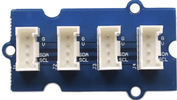
Pin Configuration and Descriptions
The pinout of an I2C hub may vary depending on the model. Below is a typical pin configuration:
| Pin Name | Description |
|---|---|
| VCC | Power supply input (3.3V or 5V, depending on the hub). |
| GND | Ground connection. |
| SDA | Serial Data Line for the I2C bus (connects to the master SDA line). |
| SCL | Serial Clock Line for the I2C bus (connects to the master SCL line). |
| CH1_SDA | SDA line for Channel 1 (connects to the SDA of the first slave device). |
| CH1_SCL | SCL line for Channel 1 (connects to the SCL of the first slave device). |
| CH2_SDA | SDA line for Channel 2 (connects to the SDA of the second slave device). |
| CH2_SCL | SCL line for Channel 2 (connects to the SCL of the second slave device). |
| ... | Additional channels follow the same pattern (e.g., CH3_SDA, CH3_SCL, etc.). |
| ADDR | Optional pin for setting the hub's I2C address (if configurable). |
Usage Instructions
How to Use the I2C Hub in a Circuit
- Power the Hub: Connect the VCC and GND pins of the hub to the power supply of your system (3.3V or 5V).
- Connect the Master Device: Attach the SDA and SCL lines of the I2C hub to the corresponding SDA and SCL lines of the master device (e.g., Arduino, Raspberry Pi).
- Connect Slave Devices: Connect the SDA and SCL lines of each slave device to the appropriate channel on the hub (e.g., CH1_SDA, CH1_SCL for Channel 1).
- Address Configuration: If the hub supports address configuration, set the desired address using the ADDR pin or other configuration methods (refer to the hub's datasheet).
- Enable Pull-Up Resistors: Ensure that pull-up resistors are present on the SDA and SCL lines if not already included in the hub.
Important Considerations and Best Practices
- Address Conflicts: Use the hub's address isolation feature to avoid conflicts between devices with the same I2C address.
- Signal Integrity: For long bus lines, ensure proper termination and consider using hubs with signal buffering.
- Voltage Compatibility: Verify that all devices on the I2C bus operate at the same voltage level (3.3V or 5V).
- I2C Speed: Ensure that all devices on the bus support the same I2C speed (e.g., 100 kHz or 400 kHz).
Example: Using an I2C Hub with Arduino UNO
Below is an example of how to use an I2C hub to connect multiple devices to an Arduino UNO:
Circuit Connections
- Connect the I2C hub's VCC and GND to the Arduino's 5V and GND pins.
- Connect the hub's SDA and SCL pins to the Arduino's A4 (SDA) and A5 (SCL) pins.
- Connect the slave devices to the hub's channels (e.g., CH1_SDA, CH1_SCL, etc.).
Arduino Code Example
#include <Wire.h>

// Define I2C addresses for the slave devices
#define DEVICE1_ADDR 0x40  // Example address for device 1
#define DEVICE2_ADDR 0x41  // Example address for device 2

void setup() {
  Wire.begin();  // Initialize I2C communication
  Serial.begin(9600);  // Start serial communication for debugging

  // Check communication with Device 1
  Wire.beginTransmission(DEVICE1_ADDR);
  if (Wire.endTransmission() == 0) {
    Serial.println("Device 1 connected successfully!");
  } else {
    Serial.println("Failed to connect to Device 1.");
  }

  // Check communication with Device 2
  Wire.beginTransmission(DEVICE2_ADDR);
  if (Wire.endTransmission() == 0) {
    Serial.println("Device 2 connected successfully!");
  } else {
    Serial.println("Failed to connect to Device 2.");
  }
}

void loop() {
  // Example: Read data from Device 1
  Wire.requestFrom(DEVICE1_ADDR, 1);  // Request 1 byte from Device 1
  if (Wire.available()) {
    int data = Wire.read();  // Read the received byte
    Serial.print("Data from Device 1: ");
    Serial.println(data);
  }

  delay(1000);  // Wait 1 second before the next read
}
Troubleshooting and FAQs
Common Issues and Solutions
Devices Not Responding:
- Cause: Incorrect wiring or address conflict.
- Solution: Double-check the wiring and ensure that each device has a unique address.
Data Corruption:
- Cause: Signal integrity issues on long bus lines.
- Solution: Use a hub with signal buffering or add external pull-up resistors.
Voltage Mismatch:
- Cause: Devices operating at different voltage levels (e.g., 3.3V vs. 5V).
- Solution: Use level shifters or ensure all devices operate at the same voltage.
Hub Not Detected:
- Cause: Incorrect power supply or configuration.
- Solution: Verify the hub's power supply and configuration settings.
FAQs
Can I connect devices with the same I2C address to the hub? Yes, most I2C hubs support address isolation, allowing devices with the same address to operate on separate channels.
Do I need external pull-up resistors? Many hubs include built-in pull-up resistors, but you may need to add external ones for long bus lines or high-speed communication.
What is the maximum number of devices I can connect? This depends on the number of channels on the hub and the electrical limitations of the I2C bus. Check the hub's datasheet for details.