How to Use 7805: Examples, Pinouts, and Specs
Introduction
The 7805 is a widely used linear voltage regulator that outputs a stable 5V DC from a higher input voltage, typically ranging from 7V to 35V. This component is essential in many electronic devices, ensuring that sensitive electronic circuits receive a constant voltage, which is crucial for reliable operation. Common applications include power supplies for microcontrollers, small motors, and other digital logic circuits.
Explore Projects Built with 7805

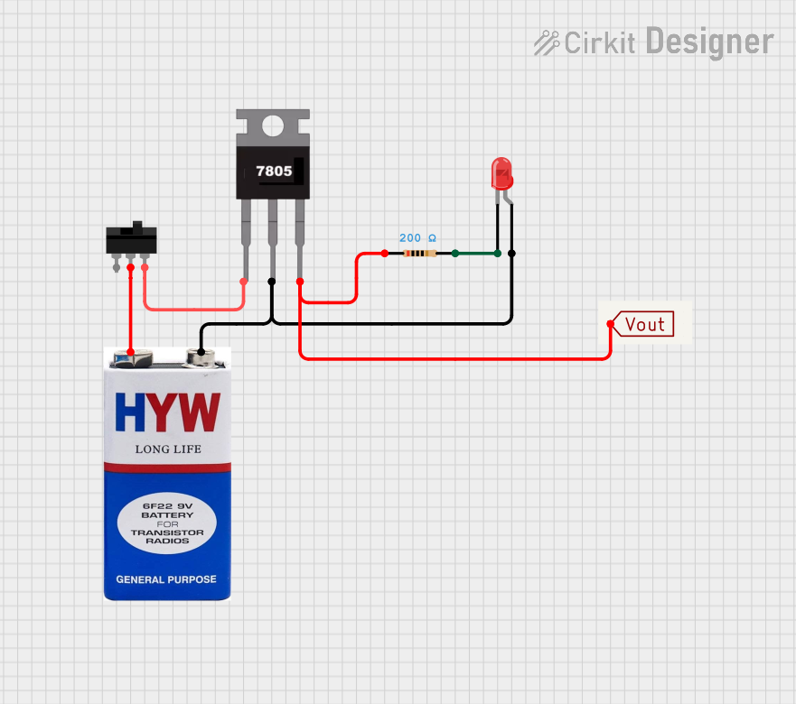
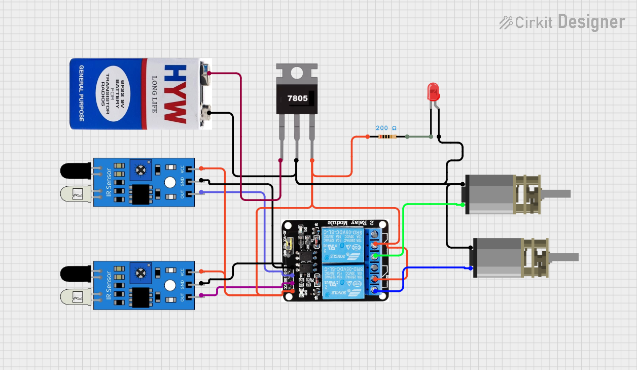

Explore Projects Built with 7805
Technical Specifications
Key Technical Details
- Output Voltage: 5V
- Input Voltage (recommended): 7V to 25V
- Input Voltage (maximum): 35V
- Output Current (maximum): 1A (with adequate heat sinking)
- Quiescent Current: 5mA (typical)
- Dropout Voltage: 2V (typical at full load)
- Short Circuit Protection: Yes
- Thermal Overload Protection: Yes
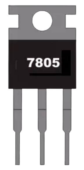
- Package: TO-220 (commonly used)
Pin Configuration and Descriptions
| Pin Number | Name | Description |
|---|---|---|
| 1 | Input | The input pin where the unregulated voltage is applied. |
| 2 | Ground | Common ground for both the input and output voltage. |
| 3 | Output | The regulated 5V output voltage pin. |
Usage Instructions
Incorporating the 7805 into a Circuit
- Connect the input voltage to pin 1 of the 7805. Ensure that the voltage is within the recommended range.
- Connect pin 2 to the ground of your power source and the ground of your circuit.
- Connect pin 3 to the power input of your 5V circuit.
- It is recommended to place a 0.33uF ceramic capacitor between the input pin and ground to filter input noise.
- Place a 0.1uF ceramic capacitor between the output pin and ground to improve transient response.
Important Considerations and Best Practices
- Always use capacitors on the input and output as specified to minimize voltage fluctuations.
- Ensure the input voltage is always at least 2V greater than the output voltage to maintain regulation.
- Provide adequate heat sinking if the regulator is expected to handle currents near 1A, as it will dissipate heat.
- Avoid reverse polarity; it can damage the regulator.
- Keep the regulator away from high-frequency switching components to prevent interference.
Troubleshooting and FAQs
Common Issues
- Voltage Drop: If the output voltage is lower than 5V, check the input voltage and ensure it is at least 2V above the desired output.
- Overheating: If the regulator is too hot, improve heat sinking or reduce the load current.
- No Output: Ensure the input is connected correctly and that there are no short circuits on the output.
FAQs
Q: Can I use the 7805 without capacitors? A: It is not recommended as the capacitors help to maintain a stable output voltage and reduce noise.
Q: What is the maximum input voltage for the 7805? A: The absolute maximum input voltage is 35V, but it is recommended to keep it at 25V or below for reliable operation.
Q: How can I increase the output current? A: You can parallel multiple 7805 regulators with diodes on the outputs to prevent backfeeding, but this is not an ideal solution. Consider using a switching regulator for higher currents.
Q: Can the 7805 be used with an Arduino UNO? A: Yes, the 7805 can be used to provide a stable 5V supply to an Arduino UNO or any other microcontroller that operates at 5V.
Example Arduino Connection
// No specific code is required for using the 7805 with an Arduino UNO.
// Simply connect the 7805 regulated 5V output to the 5V pin on the Arduino,
// and the ground from the 7805 to the GND pin on the Arduino.

void setup() {
  // Initialize digital pin LED_BUILTIN as an output.
  pinMode(LED_BUILTIN, OUTPUT);
}

void loop() {
  // Turn the LED on (HIGH is the voltage level)
  digitalWrite(LED_BUILTIN, HIGH);
  // Wait for a second
  delay(1000);
  // Turn the LED off by making the voltage LOW
  digitalWrite(LED_BUILTIN, LOW);
   // Wait for a second
  delay(1000);
}
Note: The above code is a simple blink program to test the functionality of the Arduino UNO when powered by the 7805 voltage regulator. The 7805 itself does not require any code to operate.