Cirkit Designer Logo
Cirkit Designer
Your all-in-one circuit design IDE
Home / 
Component Documentation

How to Use WLC Omron 61f-g-ap: Examples, Pinouts, and Specs

Image of WLC Omron 61f-g-ap
Cirkit Designer LogoDesign with WLC Omron 61f-g-ap in Cirkit Designer

Introduction

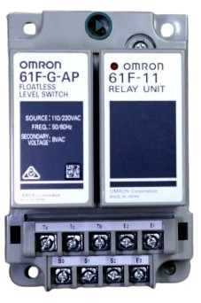
The WLC Omron 61F-G-AP is a liquid level controller designed for monitoring and controlling the level of liquids in various applications. It is widely used in industrial environments due to its compact design, high reliability, and robust performance. This component is ideal for applications such as water supply systems, wastewater management, and industrial liquid level monitoring.

Explore Projects Built with WLC Omron 61f-g-ap

Use Cirkit Designer to design, explore, and prototype these projects online. Some projects support real-time simulation. Click "Open Project" to start designing instantly!
Arduino UNO Based Automated Plant Watering System with Environmental Monitoring
Image of Automatisierungsprojekt: A project utilizing WLC Omron 61f-g-ap in a practical application
This circuit is designed to monitor environmental conditions and control peripheral devices. It features light and temperature/humidity sensing, visual output on an OLED display, and actuation of a fan, water pumps, and a stepper motor. Power management and distribution are facilitated by splicing connectors, and the system is controlled by an Arduino UNO, which currently has placeholder code for customization.
Cirkit Designer LogoOpen Project in Cirkit Designer
NFC-Enabled Access Control System with Real-Time Clock and OLED Display
Image of doorlock: A project utilizing WLC Omron 61f-g-ap in a practical application
This circuit is designed as an access control system with time-tracking capabilities. It uses an NFC/RFID reader for authentication, a real-time clock for time-stamping events, and an OLED display for user interface, all controlled by a T8_S3 microcontroller. A relay module actuates a magnetic lock, and a button switch provides additional user input, with a switching power supply delivering the necessary voltages.
Cirkit Designer LogoOpen Project in Cirkit Designer
Battery-Powered Health Monitoring System with Nucleo WB55RG and OLED Display
Image of Pulsefex: A project utilizing WLC Omron 61f-g-ap in a practical application
This circuit is a multi-sensor data acquisition system that uses a Nucleo WB55RG microcontroller to interface with a digital temperature sensor (TMP102), a pulse oximeter and heart-rate sensor (MAX30102), and a 0.96" OLED display via I2C. Additionally, it includes a Sim800l module for GSM communication, powered by a 3.7V LiPo battery.
Cirkit Designer LogoOpen Project in Cirkit Designer
NFC-Enabled Access Control System with Time Logging
Image of doorlock: A project utilizing WLC Omron 61f-g-ap in a practical application
This circuit is designed for access control with time tracking capabilities. It features an NFC/RFID reader for authentication, an RTC module (DS3231) for real-time clock functionality, and an OLED display for user interaction. A 12V relay controls a magnetic lock, which is activated upon successful NFC/RFID authentication, and a button switch is likely used for manual operation or input. The T8_S3 microcontroller serves as the central processing unit, interfacing with the NFC/RFID reader, RTC, OLED, and relay to manage the access control logic.
Cirkit Designer LogoOpen Project in Cirkit Designer

Explore Projects Built with WLC Omron 61f-g-ap

Use Cirkit Designer to design, explore, and prototype these projects online. Some projects support real-time simulation. Click "Open Project" to start designing instantly!
Image of Automatisierungsprojekt: A project utilizing WLC Omron 61f-g-ap in a practical application
Arduino UNO Based Automated Plant Watering System with Environmental Monitoring
This circuit is designed to monitor environmental conditions and control peripheral devices. It features light and temperature/humidity sensing, visual output on an OLED display, and actuation of a fan, water pumps, and a stepper motor. Power management and distribution are facilitated by splicing connectors, and the system is controlled by an Arduino UNO, which currently has placeholder code for customization.
Cirkit Designer LogoOpen Project in Cirkit Designer
Image of doorlock: A project utilizing WLC Omron 61f-g-ap in a practical application
NFC-Enabled Access Control System with Real-Time Clock and OLED Display
This circuit is designed as an access control system with time-tracking capabilities. It uses an NFC/RFID reader for authentication, a real-time clock for time-stamping events, and an OLED display for user interface, all controlled by a T8_S3 microcontroller. A relay module actuates a magnetic lock, and a button switch provides additional user input, with a switching power supply delivering the necessary voltages.
Cirkit Designer LogoOpen Project in Cirkit Designer
Image of Pulsefex: A project utilizing WLC Omron 61f-g-ap in a practical application
Battery-Powered Health Monitoring System with Nucleo WB55RG and OLED Display
This circuit is a multi-sensor data acquisition system that uses a Nucleo WB55RG microcontroller to interface with a digital temperature sensor (TMP102), a pulse oximeter and heart-rate sensor (MAX30102), and a 0.96" OLED display via I2C. Additionally, it includes a Sim800l module for GSM communication, powered by a 3.7V LiPo battery.
Cirkit Designer LogoOpen Project in Cirkit Designer
Image of doorlock: A project utilizing WLC Omron 61f-g-ap in a practical application
NFC-Enabled Access Control System with Time Logging
This circuit is designed for access control with time tracking capabilities. It features an NFC/RFID reader for authentication, an RTC module (DS3231) for real-time clock functionality, and an OLED display for user interaction. A 12V relay controls a magnetic lock, which is activated upon successful NFC/RFID authentication, and a button switch is likely used for manual operation or input. The T8_S3 microcontroller serves as the central processing unit, interfacing with the NFC/RFID reader, RTC, OLED, and relay to manage the access control logic.
Cirkit Designer LogoOpen Project in Cirkit Designer

Common Applications and Use Cases

  • Water Supply Systems: Automatically controls water levels in tanks and reservoirs.
  • Wastewater Management: Monitors and regulates liquid levels in treatment plants.
  • Industrial Processes: Ensures proper liquid levels in manufacturing and chemical processes.
  • Cooling Systems: Maintains liquid levels in cooling towers and heat exchangers.

Technical Specifications

The following table outlines the key technical details of the WLC Omron 61F-G-AP:

Specification Details
Power Supply Voltage 100-240 VAC
Power Consumption Approx. 3.5 VA
Operating Temperature -10°C to 55°C
Control Output SPDT relay output (5 A at 250 VAC, resistive load)
Electrode Voltage Approx. 8 VAC
Electrode Current Approx. 1 mA
Response Time Approx. 80 ms
Mounting DIN rail or screw mounting
Dimensions 49.4 mm (W) × 38 mm (H) × 84 mm (D)
Weight Approx. 120 g

Pin Configuration and Descriptions

The WLC Omron 61F-G-AP features a terminal block for wiring. Below is the pin configuration:

Terminal Description
1 Power supply input (L)
2 Power supply input (N)
3 Common terminal for electrodes
4 High-level electrode input
5 Low-level electrode input
6 Relay output (NO - Normally Open)
7 Relay output (COM - Common)
8 Relay output (NC - Normally Closed)

Usage Instructions

How to Use the Component in a Circuit

  1. Power Supply Connection: Connect terminals 1 (L) and 2 (N) to a 100-240 VAC power source.
  2. Electrode Wiring:
    • Connect the common electrode to terminal 3.
    • Connect the high-level electrode to terminal 4.
    • Connect the low-level electrode to terminal 5.
  3. Relay Output Wiring:
    • Use terminals 6 (NO), 7 (COM), and 8 (NC) to connect the relay output to your control circuit.
    • For example, connect a pump or alarm system to the relay output to control liquid levels.
  4. Mounting: Secure the controller to a DIN rail or use screws for panel mounting.

Important Considerations and Best Practices

  • Ensure the electrodes are properly installed in the liquid tank and are free from debris or corrosion.
  • Use shielded cables for electrode connections to minimize electrical noise interference.
  • Avoid using the controller in environments with excessive vibration, dust, or corrosive gases.
  • Regularly inspect and clean the electrodes to maintain accurate liquid level detection.
  • Verify that the relay output ratings match the connected load to prevent damage.

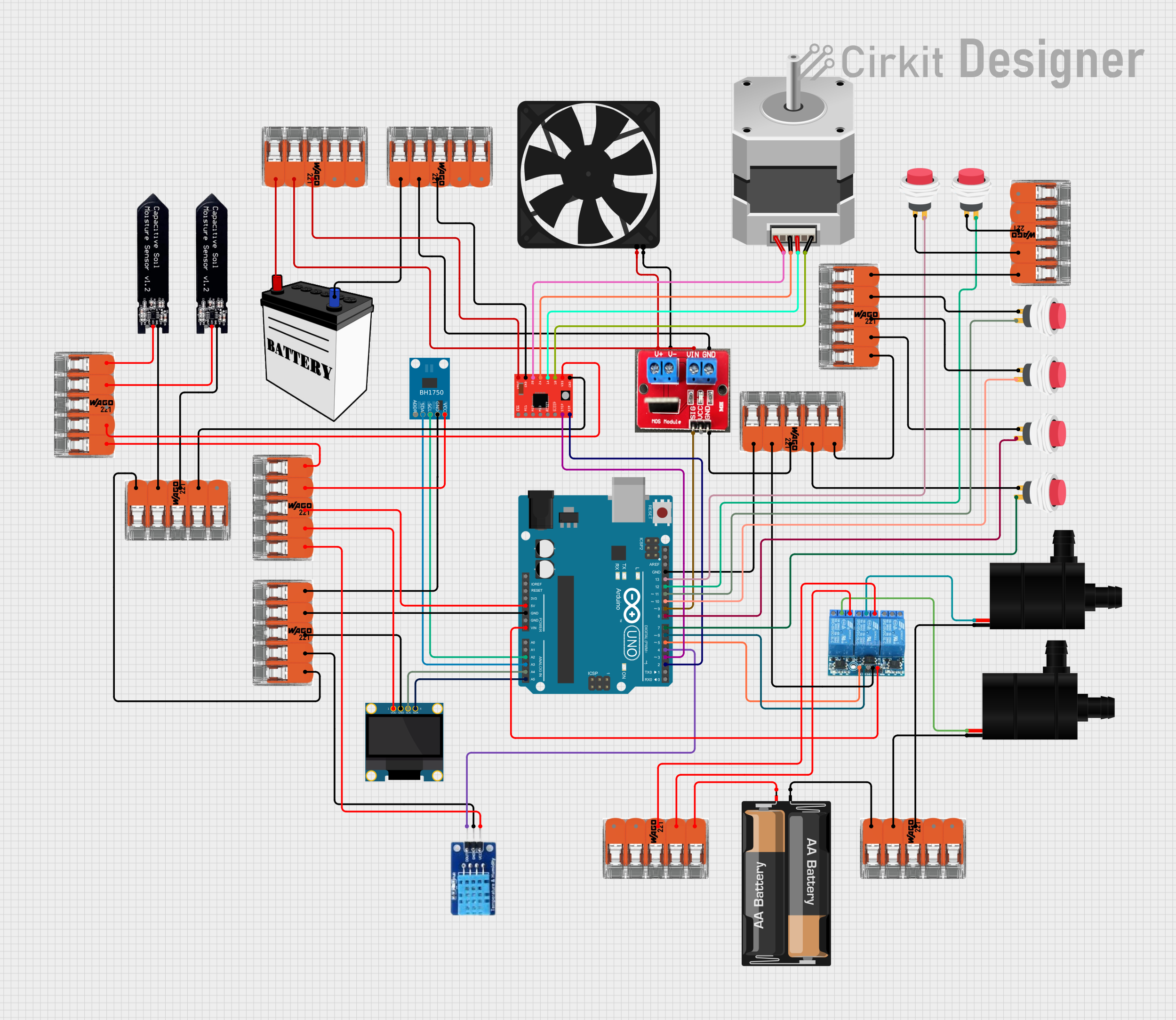
Example: Connecting to an Arduino UNO

While the WLC Omron 61F-G-AP is primarily an industrial component, it can be interfaced with an Arduino UNO for monitoring purposes. Below is an example code snippet to read the relay output:

// Define the pin connected to the relay output (NO terminal)
const int relayPin = 2;

void setup() {
  // Initialize the relay pin as an input
  pinMode(relayPin, INPUT);
  // Start the serial communication for debugging
  Serial.begin(9600);
}

void loop() {
  // Read the state of the relay output
  int relayState = digitalRead(relayPin);

  // Check if the relay is activated (liquid level detected)
  if (relayState == HIGH) {
    Serial.println("Liquid level is within the desired range.");
  } else {
    Serial.println("Liquid level is outside the desired range.");
  }

  // Add a small delay to avoid flooding the serial monitor
  delay(500);
}

Note: Use an optocoupler or relay module to safely interface the WLC Omron 61F-G-AP with the Arduino, as the relay output operates at higher voltages.

Troubleshooting and FAQs

Common Issues and Solutions

  1. The controller does not power on:

    • Verify that the power supply voltage is within the specified range (100-240 VAC).
    • Check the wiring connections to terminals 1 (L) and 2 (N).
  2. Relay output does not activate:

    • Ensure the electrodes are properly connected and submerged in the liquid.
    • Check for corrosion or debris on the electrodes and clean them if necessary.
    • Verify that the relay output wiring is correct and matches the load requirements.
  3. Erratic or false triggering:

    • Use shielded cables for electrode connections to reduce electrical noise.
    • Ensure the liquid being monitored is conductive enough for the controller to detect.
  4. Electrodes fail to detect liquid levels:

    • Confirm that the liquid is compatible with the controller (e.g., water or other conductive liquids).
    • Inspect the electrode connections and ensure they are secure.

FAQs

Q: Can the WLC Omron 61F-G-AP be used with non-conductive liquids?
A: No, this controller is designed for conductive liquids. It relies on the conductivity of the liquid to detect levels.

Q: What is the maximum cable length for electrode connections?
A: The maximum cable length depends on the installation environment, but shielded cables up to 50 meters are typically recommended.

Q: Can the controller handle high-pressure environments?
A: The controller itself is not exposed to pressure, but the electrodes must be suitable for the pressure conditions in the tank.

Q: Is the WLC Omron 61F-G-AP compatible with DC power supplies?
A: No, the controller requires an AC power supply within the range of 100-240 VAC.