Cytron is a renowned brand specializing in robotics and electronics components. Their product range includes motor drivers, sensors, and development boards, all designed to simplify the development of robotic and electronic projects. Cytron components are widely used in educational, hobbyist, and professional applications due to their reliability and ease of use.
Common applications of Cytron components include:
Motor control for robotics and automation systems
Sensor integration for environmental monitoring
Development of custom electronic projects using microcontrollers
Prototyping and educational projects in STEM fields
Explore Projects Built with cytron
Use Cirkit Designer to design, explore, and prototype these projects online. Some projects support real-time simulation. Click "Open Project" to start designing instantly!
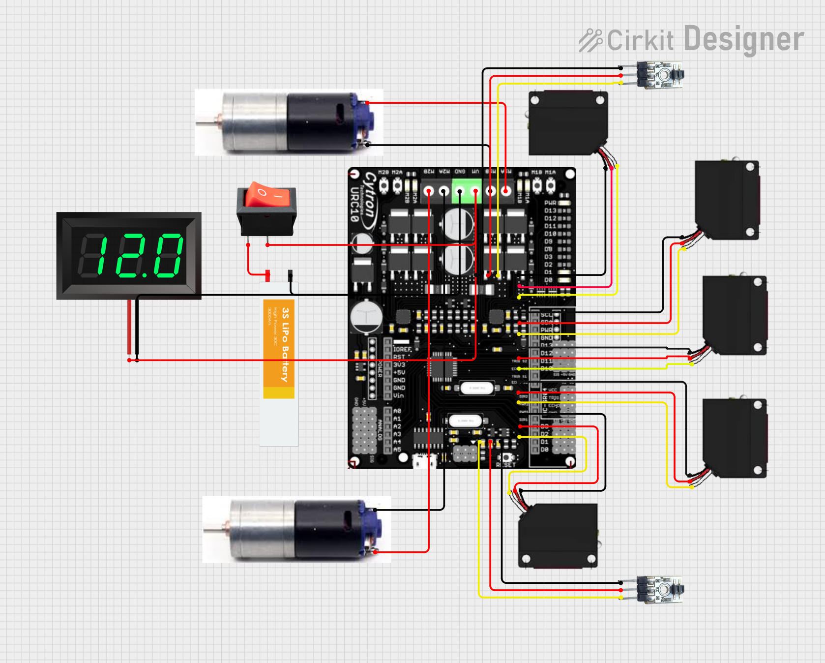
This circuit is a robotic control system that uses multiple IR sensors for line detection and obstacle avoidance, powered by a 3S LiPo battery. The Cytron URC10 motor driver, controlled by a microcontroller, drives two GM25 DC motors based on input from the sensors and a rocker switch, with a 7-segment panel voltmeter displaying the battery voltage.
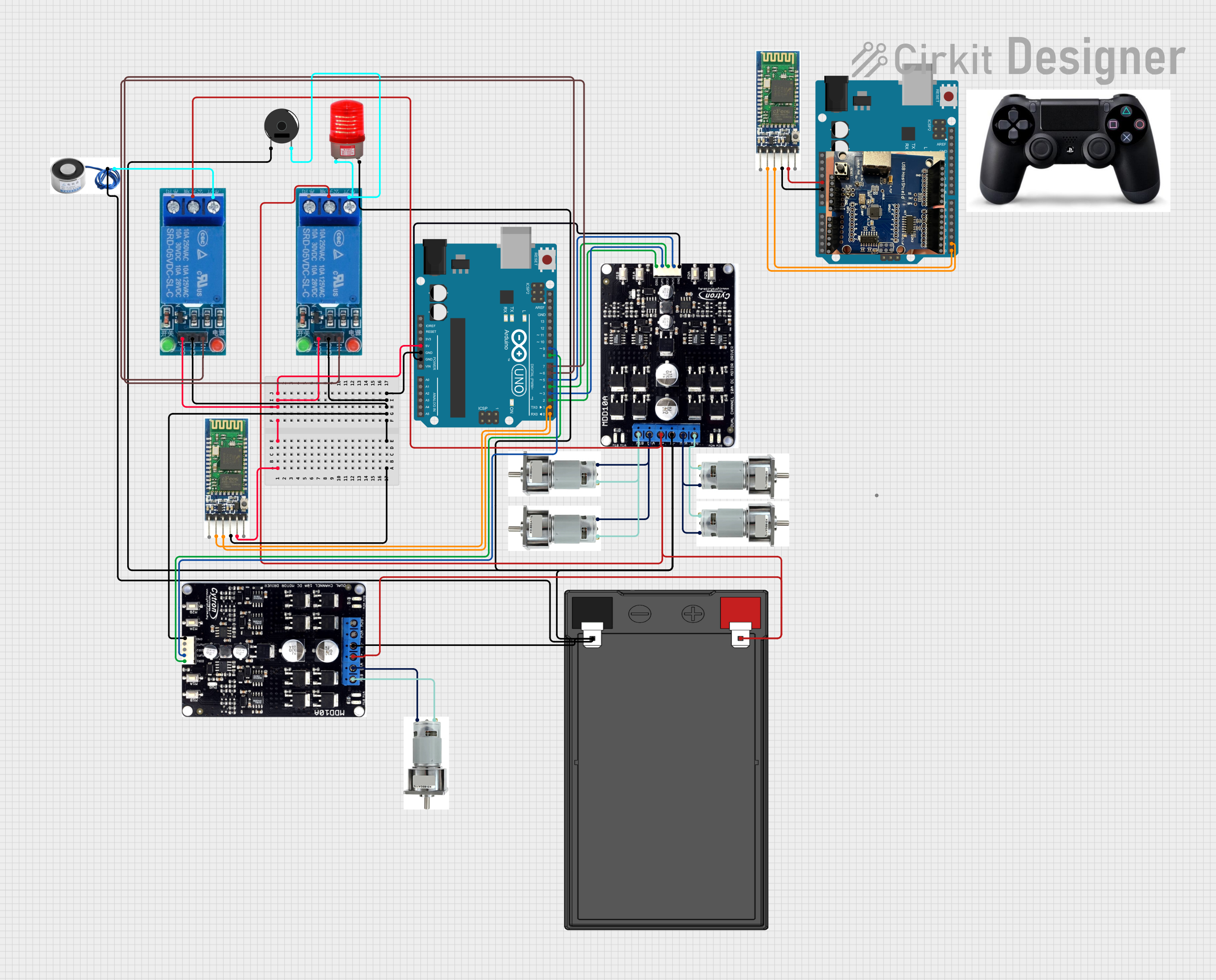
This is a motor control system with wireless communication capabilities, designed to operate multiple motors via Cytron motor drivers, controlled by Arduino UNOs. It includes relays for activating a light and buzzer, and uses Bluetooth for remote operation. The system's software is in the initial stages of development.
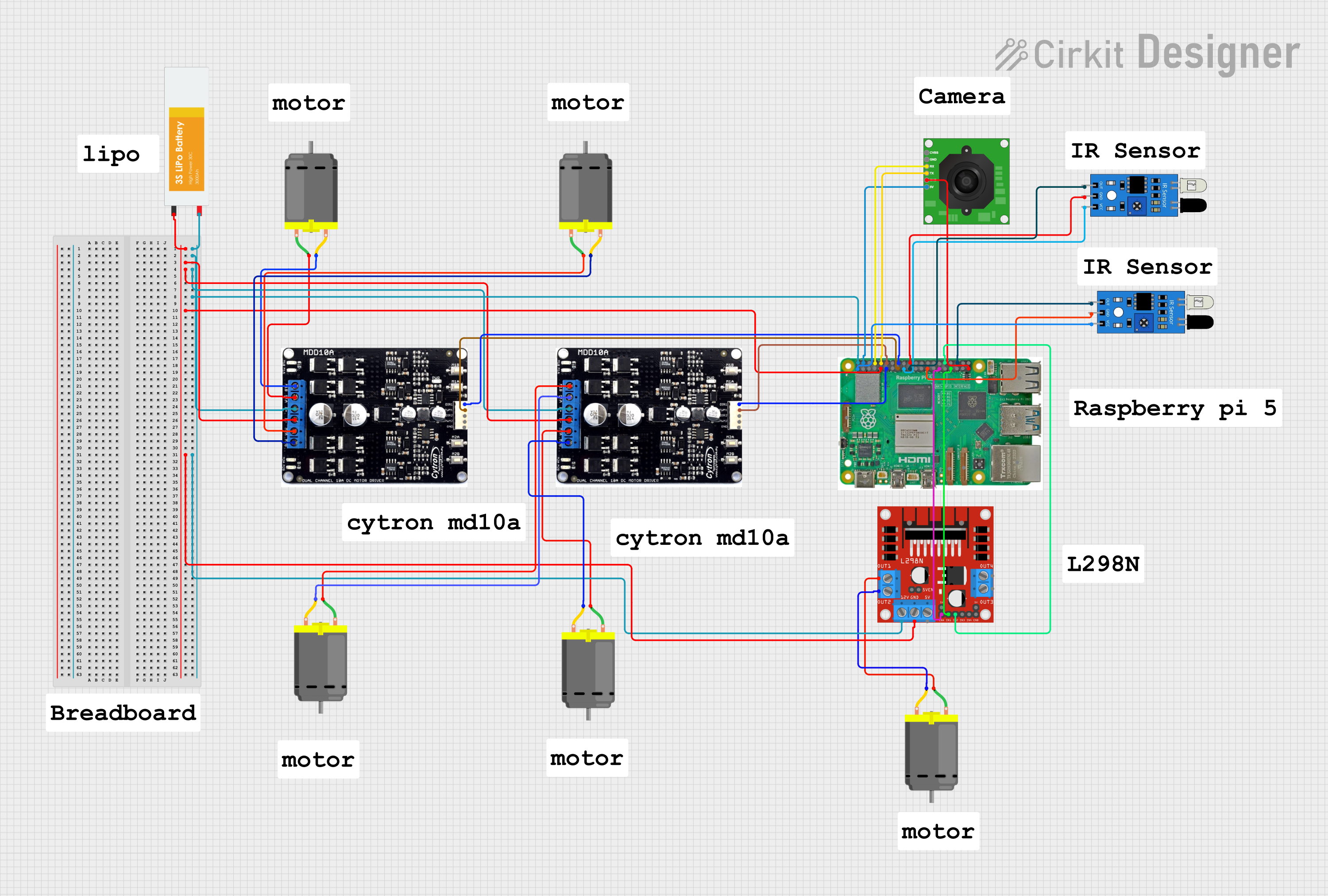
This is a motor control system for multiple DC motors, utilizing Cytron and L298N motor drivers for speed and direction control. It is managed by a Raspberry Pi 5, which also interfaces with IR sensors for object detection and a camera for image capture, indicating potential use in robotics or automated systems.
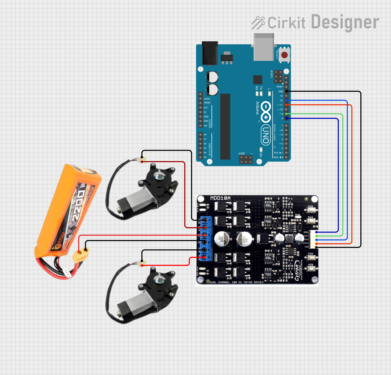
This circuit is a control system for a two-wheel mobile robot, utilizing an Arduino UNO to manage a Cytron motor driver. The Arduino controls the direction and speed of two power window motors via PWM and direction signals, powered by a LiPo battery.
Below are the general technical specifications for Cytron components. Since Cytron offers a variety of products, the specifications may vary depending on the specific component. For this documentation, we will focus on the Cytron MD10C R3 Motor Driver, a popular motor driver from Cytron.
Key Technical Details
Operating Voltage: 7V to 30V DC
Continuous Current: 10A (per channel)
Peak Current: 30A (for 10 seconds)
Control Signal Voltage: 3.3V or 5V logic compatible
PWM Frequency: Up to 20 kHz
Dimensions: 84mm x 62mm x 25mm
Weight: 70g
Pin Configuration and Descriptions
The Cytron MD10C R3 Motor Driver has the following pin configuration:
Pin Name
Description
VIN
Power input for the motor driver (7V to 30V DC).
GND
Ground connection.
PWM
Pulse Width Modulation input for speed control (3.3V or 5V logic).
DIR
Direction control input (HIGH for forward, LOW for reverse).
MOTOR+
Positive terminal of the motor.
MOTOR-
Negative terminal of the motor.
VOUT
Regulated output voltage (5V, max 1A) for powering external circuits.
Usage Instructions
How to Use the Cytron MD10C R3 Motor Driver in a Circuit
Power Supply: Connect a DC power source (7V to 30V) to the VIN and GND pins. Ensure the power supply can provide sufficient current for your motor.
Motor Connection: Connect the motor terminals to the MOTOR+ and MOTOR- pins.
Control Signals:
Connect the PWM pin to a PWM-capable pin on your microcontroller (e.g., Arduino).
Connect the DIR pin to a digital output pin on your microcontroller to control the motor's direction.
Logic Voltage: The MD10C R3 is compatible with both 3.3V and 5V logic levels, making it suitable for a wide range of microcontrollers.
Optional Output: Use the VOUT pin to power external circuits if needed (e.g., sensors or microcontrollers).
Important Considerations and Best Practices
Heat Dissipation: The motor driver can handle high currents, but prolonged operation at high currents may cause overheating. Use a heatsink or active cooling if necessary.
Current Limiting: Ensure the motor's current draw does not exceed the driver's maximum continuous current rating (10A).
PWM Frequency: Use a PWM frequency of up to 20 kHz for optimal performance.
Reverse Polarity Protection: The MD10C R3 includes reverse polarity protection, but always double-check your connections to avoid damage.
Example Code for Arduino UNO
Below is an example code snippet to control a motor using the Cytron MD10C R3 Motor Driver with an Arduino UNO:
// Define pin connections
const int pwmPin = 9;  // PWM pin connected to MD10C R3's PWM input
const int dirPin = 8;  // Direction pin connected to MD10C R3's DIR input

void setup() {
  // Set pin modes
  pinMode(pwmPin, OUTPUT);
  pinMode(dirPin, OUTPUT);
}

void loop() {
  // Rotate motor forward at 50% speed
  digitalWrite(dirPin, HIGH);  // Set direction to forward
  analogWrite(pwmPin, 128);    // Set PWM duty cycle to 50% (128/255)
  delay(2000);                 // Run for 2 seconds

  // Rotate motor backward at 75% speed
  digitalWrite(dirPin, LOW);   // Set direction to reverse
  analogWrite(pwmPin, 192);    // Set PWM duty cycle to 75% (192/255)
  delay(2000);                 // Run for 2 seconds

  // Stop the motor
  analogWrite(pwmPin, 0);      // Set PWM duty cycle to 0 (stop)
  delay(2000);                 // Wait for 2 seconds
}
Troubleshooting and FAQs
Common Issues and Solutions
Motor Not Spinning:
Check the power supply voltage and ensure it is within the 7V to 30V range.
Verify the motor connections to the MOTOR+ and MOTOR- pins.
Ensure the PWM and DIR pins are correctly connected to the microcontroller.
Motor Spins in the Wrong Direction:
Reverse the logic level on the DIR pin (HIGH to LOW or vice versa).
Alternatively, swap the MOTOR+ and MOTOR- connections.
Overheating:
Ensure the motor's current draw does not exceed the driver's continuous current rating.
Add a heatsink or active cooling to the motor driver.
PWM Signal Not Detected:
Verify that the microcontroller is outputting a PWM signal on the specified pin.
Check the PWM frequency and ensure it does not exceed 20 kHz.
FAQs
Can I use the MD10C R3 with a 3.3V microcontroller?
Yes, the MD10C R3 is compatible with both 3.3V and 5V logic levels.
What type of motors can I control with this driver?
The MD10C R3 is designed for brushed DC motors.
Is reverse polarity protection included?
Yes, the MD10C R3 includes reverse polarity protection for the power input.
Can I control two motors with this driver?
No, the MD10C R3 is a single-channel motor driver and can control only one motor. For dual-motor control, consider Cytron's dual-channel motor drivers.
This documentation provides a comprehensive guide to using the Cytron MD10C R3 Motor Driver. For further assistance, refer to the official Cytron website or contact their support team.

 Open Project in Cirkit Designer