
How to Use JeeNode wireless microcontroller: Examples, Pinouts, and Specs
 Design with JeeNode wireless microcontroller in Cirkit Designer
Introduction
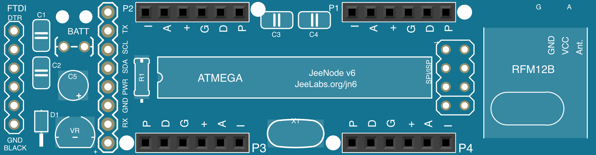
The JeeNode Wireless Microcontroller, developed by JeeLabs, is a compact, low-power microcontroller board designed specifically for wireless communication. It is widely used in Internet of Things (IoT) applications due to its integrated radio module, which simplifies connectivity. The JeeNode is compatible with a variety of sensors and actuators, making it an excellent choice for projects requiring remote monitoring, data collection, or control.
Explore Projects Built with JeeNode wireless microcontroller
 Open Project in Cirkit Designer
 Open Project in Cirkit Designer
 Open Project in Cirkit Designer
 Open Project in Cirkit Designer
Explore Projects Built with JeeNode wireless microcontroller
Open Project in Cirkit DesignerOpen Project in Cirkit DesignerOpen Project in Cirkit DesignerOpen Project in Cirkit DesignerCommon Applications and Use Cases
- Home automation systems
- Environmental monitoring (e.g., temperature, humidity, air quality)
- Wireless sensor networks
- Remote control of devices
- IoT prototyping and development
Technical Specifications
The JeeNode Wireless Microcontroller is based on the ATmega328P microcontroller and features an integrated RFM12B or RFM69 wireless radio module. Below are the key technical details:
General Specifications
| Parameter | Value |
|---|---|
| Microcontroller | ATmega328P |
| Operating Voltage | 3.3V |
| Clock Speed | 16 MHz (external resonator) |
| Flash Memory | 32 KB (2 KB used by bootloader) |
| SRAM | 2 KB |
| EEPROM | 1 KB |
| Wireless Module | RFM12B or RFM69 |
| Communication Range | Up to 300 meters (line of sight) |
| Power Consumption | ~10 µA in sleep mode |
| Dimensions | 2.0 x 1.0 inches |
Pin Configuration and Descriptions
The JeeNode features four ports (Port 1 to Port 4), each with a standardized pinout for easy connection to sensors and actuators. Additionally, it includes power and programming pins.
Port Pinout
| Pin Name | Description |
|---|---|
| DIO | Digital Input/Output |
| AIO | Analog Input/Output |
| PWR | Power (3.3V) |
| GND | Ground |
Power and Programming Pins
| Pin Name | Description |
|---|---|
| VCC | 3.3V Power Supply |
| GND | Ground |
| FTDI | Serial programming header (6 pins) |
Usage Instructions
How to Use the JeeNode in a Circuit
Powering the JeeNode:
- Supply 3.3V to the VCC pin. The board can be powered via a battery, USB-to-serial adapter, or a regulated power supply.
- Ensure the power source can provide sufficient current for both the microcontroller and the wireless module.
Connecting Sensors and Actuators:
- Use the four ports (Port 1 to Port 4) to connect sensors or actuators. Each port provides a standardized pinout (DIO, AIO, PWR, GND).
- For analog sensors, connect the signal line to the AIO pin. For digital sensors or actuators, use the DIO pin.
Programming the JeeNode:
- Use an FTDI-compatible USB-to-serial adapter to upload code to the JeeNode. Connect the adapter to the FTDI header on the board.
- Select "Arduino Pro or Pro Mini (3.3V, 8 MHz) w/ ATmega328" as the board type in the Arduino IDE.
Wireless Communication:
- The integrated RFM12B or RFM69 module allows for wireless communication. Use libraries such as JeeLib to simplify radio communication.
Example Code for Arduino IDE
Below is an example of how to send and receive data wirelessly using the JeeNode and the JeeLib library:
#include <JeeLib.h>  // Include the JeeLib library for wireless communication

#define NODE_ID 1    // Unique ID for this JeeNode
#define NETWORK_ID 100 // Network group ID
#define GATEWAY_ID 0  // ID of the receiving node (e.g., gateway)

void setup() {
  rf12_initialize(NODE_ID, RF12_868MHZ, NETWORK_ID);
  // Initialize the RFM12B module with the node ID, frequency, and network ID

  Serial.begin(9600); // Start serial communication for debugging
  Serial.println("JeeNode initialized");
}

void loop() {
  // Send a message to the gateway
  const char *message = "Hello, Gateway!";
  rf12_sendStart(RF12_HDR_ACK | GATEWAY_ID, message, strlen(message));
  rf12_sendWait(0); // Wait for the transmission to complete

  Serial.println("Message sent: Hello, Gateway!");

  delay(1000); // Wait 1 second before sending the next message
}
Important Considerations and Best Practices
- Power Supply: Ensure the power supply is stable and within the 3.3V range. Exceeding this voltage may damage the board.
- Antenna Placement: For optimal wireless performance, position the antenna away from metal objects and other sources of interference.
- Sleep Mode: Use the low-power sleep mode to extend battery life in IoT applications.
- Library Compatibility: Use the JeeLib library for seamless integration with the RFM12B or RFM69 module.
Troubleshooting and FAQs
Common Issues and Solutions
The JeeNode is not responding to uploaded code:
- Ensure the correct board type ("Arduino Pro or Pro Mini (3.3V, 8 MHz) w/ ATmega328") is selected in the Arduino IDE.
- Verify the FTDI adapter is properly connected to the FTDI header.
Wireless communication is not working:
- Check that the node ID, network ID, and frequency match between the sender and receiver.
- Ensure the antenna is properly connected and positioned.
The board is not powering on:
- Verify the power supply voltage is 3.3V.
- Check for loose or incorrect connections to the VCC and GND pins.
FAQs
Q: Can the JeeNode operate at 5V?
A: No, the JeeNode is designed to operate at 3.3V. Supplying 5V may damage the board.
Q: What is the maximum range of the wireless module?
A: The RFM12B or RFM69 module can achieve a range of up to 300 meters in line-of-sight conditions. Obstacles and interference may reduce this range.
Q: Is the JeeNode compatible with Arduino libraries?
A: Yes, the JeeNode is based on the ATmega328P microcontroller and is compatible with most Arduino libraries, including the JeeLib library for wireless communication.
Q: Can I use the JeeNode for battery-powered applications?
A: Yes, the JeeNode is optimized for low-power operation and is ideal for battery-powered IoT projects. Use sleep mode to maximize battery life.