How to Use Potentiometer(smaller): Examples, Pinouts, and Specs
Introduction
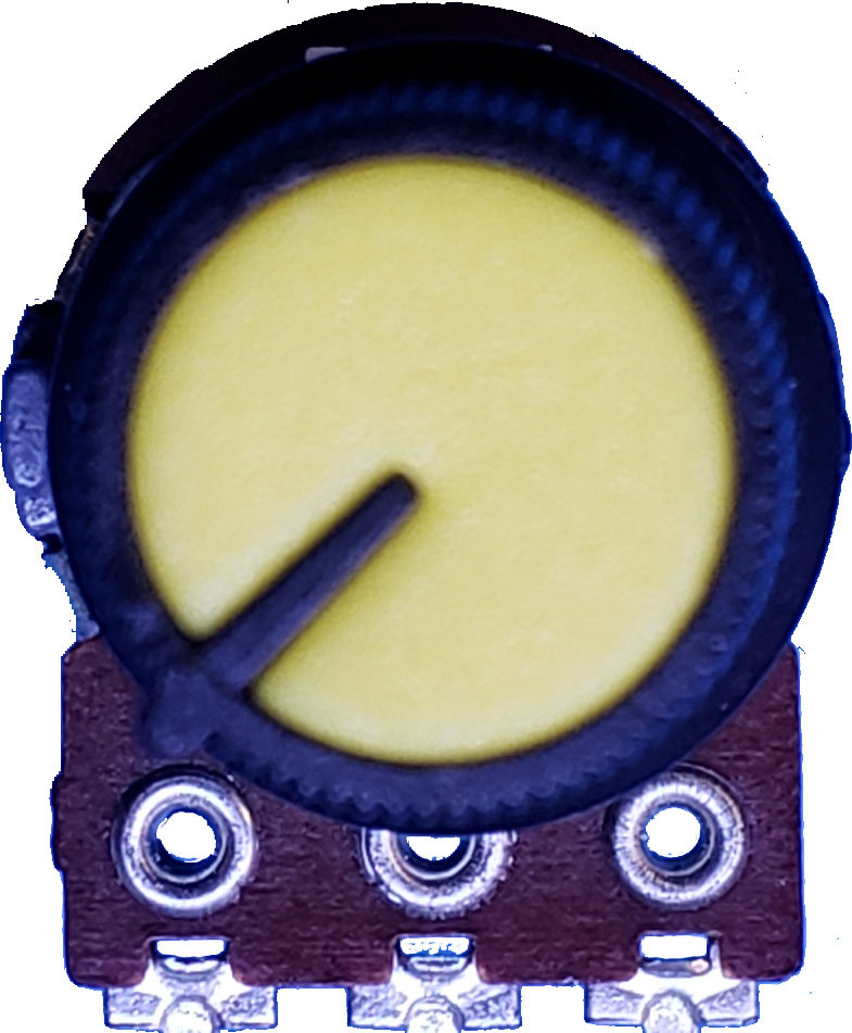
A potentiometer, often referred to as a "pot," is a variable resistor that allows users to adjust voltage levels in a circuit. It features a rotating or sliding contact that changes the resistance between its terminals. This smaller version of the potentiometer is compact and ideal for applications where space is limited.
Explore Projects Built with Potentiometer(smaller)

Explore Projects Built with Potentiometer(smaller)
Common Applications and Use Cases
- Volume control in audio devices
- Brightness adjustment in LED circuits
- Calibration and tuning in electronic circuits
- Voltage divider in analog circuits
- Input control for microcontroller-based projects (e.g., Arduino)
Technical Specifications
- Resistance Range: Typically 1 kΩ to 100 kΩ (varies by model)
- Power Rating: 0.1 W to 0.5 W
- Adjustment Type: Rotary or linear sliding
- Tolerance: ±10% to ±20%
- Operating Voltage: Up to 50 V DC
- Operating Temperature: -10°C to +70°C
- Lifespan: Approximately 10,000 to 50,000 cycles (depending on usage)
Pin Configuration and Descriptions
The potentiometer has three pins, as described below:
| Pin Number | Name | Description |
|---|---|---|
| 1 | Terminal 1 | One end of the resistive track. Connect to the voltage source or ground. |
| 2 | Wiper | The adjustable middle pin. Outputs the variable voltage based on rotation. |
| 3 | Terminal 2 | The other end of the resistive track. Connect to ground or voltage source. |
Usage Instructions
How to Use the Potentiometer in a Circuit
Voltage Divider Configuration:
- Connect Terminal 1 to the voltage source (e.g., 5V).
- Connect Terminal 3 to ground (GND).
- The Wiper (Terminal 2) will output a variable voltage between 0V and the source voltage, depending on the position of the knob or slider.
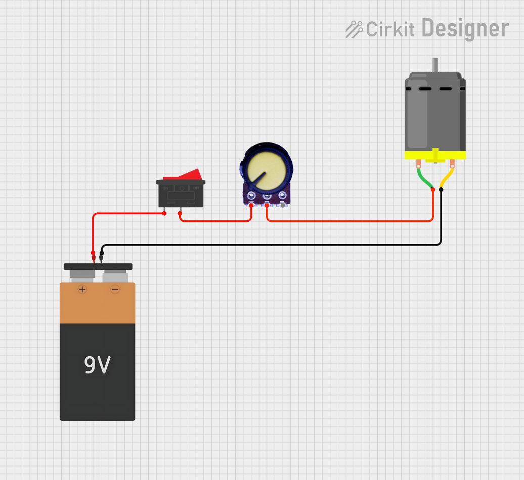
Variable Resistor Configuration:
- Connect Terminal 1 to one end of the circuit.
- Connect Terminal 2 (Wiper) to the other end of the circuit.
- Leave Terminal 3 unconnected. Adjusting the potentiometer changes the resistance between Terminal 1 and Terminal 2.
Important Considerations and Best Practices
- Avoid exceeding the power rating of the potentiometer to prevent damage.
- Use a multimeter to measure the resistance range before integrating it into your circuit.
- For precise adjustments, consider using a multi-turn potentiometer.
- When using with microcontrollers like Arduino, ensure the potentiometer's output voltage does not exceed the microcontroller's input voltage range (e.g., 0-5V for Arduino UNO).
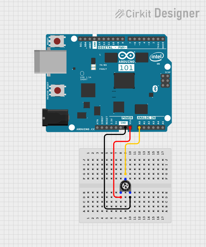
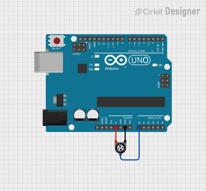
Example: Connecting to an Arduino UNO
The potentiometer can be used to provide an analog input to an Arduino UNO. Below is an example circuit and code:
Circuit Connections
- Connect Terminal 1 to 5V on the Arduino.
- Connect Terminal 3 to GND on the Arduino.
- Connect Terminal 2 (Wiper) to an analog input pin (e.g., A0) on the Arduino.
Arduino Code
// Potentiometer Example with Arduino UNO
// Reads the potentiometer value and outputs it to the Serial Monitor.

const int potPin = A0; // Define the analog pin connected to the potentiometer
int potValue = 0;      // Variable to store the potentiometer value

void setup() {
  Serial.begin(9600); // Initialize serial communication at 9600 baud
}

void loop() {
  potValue = analogRead(potPin); // Read the analog value from the potentiometer
  Serial.print("Potentiometer Value: ");
  Serial.println(potValue); // Print the value to the Serial Monitor
  delay(100); // Small delay for stability
}
Troubleshooting and FAQs
Common Issues and Solutions
No Output Voltage from the Wiper:
- Cause: Incorrect wiring or loose connections.
- Solution: Double-check the connections. Ensure Terminal 1 and Terminal 3 are connected to the voltage source and ground, respectively.
Inconsistent or Noisy Output:
- Cause: Dust or wear on the resistive track.
- Solution: Clean the potentiometer with compressed air or replace it if worn out.
Potentiometer Gets Hot:
- Cause: Exceeding the power rating.
- Solution: Use a potentiometer with a higher power rating or reduce the current in the circuit.
Arduino Reads Incorrect Values:
- Cause: Voltage from the potentiometer exceeds the Arduino's input range.
- Solution: Ensure the potentiometer's output voltage is within 0-5V for Arduino UNO.
FAQs
Q: Can I use a potentiometer to control an LED's brightness?
A: Yes, you can use a potentiometer to adjust the voltage or current supplied to the LED, often in combination with a transistor or PWM control.Q: How do I know the resistance value of my potentiometer?
A: The resistance value is usually printed on the body of the potentiometer (e.g., "10k" for 10 kΩ). You can also measure it with a multimeter.Q: Can I use a potentiometer as a switch?
A: Not directly. However, you can use it to create a threshold voltage that triggers a digital input when combined with a comparator circuit.Q: What is the difference between a linear and logarithmic potentiometer?
A: A linear potentiometer changes resistance proportionally to the rotation angle, while a logarithmic potentiometer changes resistance exponentially, often used in audio applications.