Cirkit Designer Logo
Cirkit Designer
Your all-in-one circuit design IDE
Home / 
Component Documentation

How to Use COPPER COIL - 30 TURNS: Examples, Pinouts, and Specs

Image of COPPER COIL - 30 TURNS
Cirkit Designer LogoDesign with COPPER COIL - 30 TURNS in Cirkit Designer

Introduction

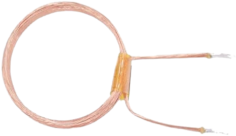
A copper coil, also known as an inductor, is a passive electronic component that consists of a wire wound into a coil. When electricity flows through the coil, it creates a magnetic field. The 30-turn copper coil is a specific type of inductor that has 30 turns of copper wire. This component is commonly used in electronic circuits for applications such as electromagnetic induction, filtering, and energy storage.

Explore Projects Built with COPPER COIL - 30 TURNS

Use Cirkit Designer to design, explore, and prototype these projects online. Some projects support real-time simulation. Click "Open Project" to start designing instantly!
Arduino-Based Wireless Power Transmission System with Copper Coils
Image of nagesh: A project utilizing COPPER COIL - 30 TURNS in a practical application
This circuit consists of multiple copper coils connected to transmitters and a receiver, likely forming a wireless power transfer or communication system. The transmitters are connected to individual coils, and the receiver is connected to another coil, facilitating the transmission and reception of signals or power wirelessly.
Cirkit Designer LogoOpen Project in Cirkit Designer
Copper Coil Multimeter Measurement Circuit
Image of rx_copper_coil: A project utilizing COPPER COIL - 30 TURNS in a practical application
This circuit consists of two copper coils connected in series, with one of the coils having additional taps for positive and negative connections. A multimeter is connected across one of the coils to measure voltage across it. The purpose of this circuit could be to demonstrate electromagnetic induction or to measure the induced voltage in one of the coils when a current flows through the other.
Cirkit Designer LogoOpen Project in Cirkit Designer
Battery-Powered DC/DC Booster with Tactile Switch Control
Image of circuit : A project utilizing COPPER COIL - 30 TURNS in a practical application
This circuit consists of a battery-powered DC/DC booster that steps up the voltage, which is then controlled by a tactile switch. The booster is connected to a copper coil, and the switch allows the user to control the output voltage from the booster.
Cirkit Designer LogoOpen Project in Cirkit Designer
LED Array with Inductive Power Transfer
Image of Wind Mill: A project utilizing COPPER COIL - 30 TURNS in a practical application
The circuit consists of multiple red two-pin LEDs connected in parallel, with all cathodes tied together and all anodes tied together. A copper coil is also connected in parallel with the LEDs. There is no control circuitry or power regulation components indicated, and no embedded code provided, suggesting this is a simple illumination circuit possibly intended for inductive power transfer given the presence of the copper coil.
Cirkit Designer LogoOpen Project in Cirkit Designer

Explore Projects Built with COPPER COIL - 30 TURNS

Use Cirkit Designer to design, explore, and prototype these projects online. Some projects support real-time simulation. Click "Open Project" to start designing instantly!
Image of nagesh: A project utilizing COPPER COIL - 30 TURNS in a practical application
Arduino-Based Wireless Power Transmission System with Copper Coils
This circuit consists of multiple copper coils connected to transmitters and a receiver, likely forming a wireless power transfer or communication system. The transmitters are connected to individual coils, and the receiver is connected to another coil, facilitating the transmission and reception of signals or power wirelessly.
Cirkit Designer LogoOpen Project in Cirkit Designer
Image of rx_copper_coil: A project utilizing COPPER COIL - 30 TURNS in a practical application
Copper Coil Multimeter Measurement Circuit
This circuit consists of two copper coils connected in series, with one of the coils having additional taps for positive and negative connections. A multimeter is connected across one of the coils to measure voltage across it. The purpose of this circuit could be to demonstrate electromagnetic induction or to measure the induced voltage in one of the coils when a current flows through the other.
Cirkit Designer LogoOpen Project in Cirkit Designer
Image of circuit : A project utilizing COPPER COIL - 30 TURNS in a practical application
Battery-Powered DC/DC Booster with Tactile Switch Control
This circuit consists of a battery-powered DC/DC booster that steps up the voltage, which is then controlled by a tactile switch. The booster is connected to a copper coil, and the switch allows the user to control the output voltage from the booster.
Cirkit Designer LogoOpen Project in Cirkit Designer
Image of Wind Mill: A project utilizing COPPER COIL - 30 TURNS in a practical application
LED Array with Inductive Power Transfer
The circuit consists of multiple red two-pin LEDs connected in parallel, with all cathodes tied together and all anodes tied together. A copper coil is also connected in parallel with the LEDs. There is no control circuitry or power regulation components indicated, and no embedded code provided, suggesting this is a simple illumination circuit possibly intended for inductive power transfer given the presence of the copper coil.
Cirkit Designer LogoOpen Project in Cirkit Designer

Common Applications and Use Cases

  • Electromagnetic projects (e.g., making electromagnets)
  • Inductive sensors
  • Radio frequency (RF) circuits
  • Power supply circuits (e.g., inductors in buck and boost converters)
  • Analog circuits (e.g., filters, oscillators)

Technical Specifications

Key Technical Details

  • Inductance: Specified in henries (H), based on the number of turns and core material
  • Wire Gauge: The thickness of the copper wire, which affects current carrying capacity
  • Core Material: The type of material around which the coil is wound (e.g., air, ferrite)
  • Resistance: The electrical resistance of the wire, typically in ohms (Ω)
  • Current Rating: The maximum current the coil can carry without overheating
  • Voltage Rating: The maximum voltage the coil can handle

Pin Configuration and Descriptions

Since a copper coil is a two-terminal component, it does not have a complex pin configuration. The two ends of the coil are simply the electrical connections.

Pin Description
1 Coil Start (Input)
2 Coil End (Output)

Usage Instructions

How to Use the Component in a Circuit

  1. Identify the Coil Terminals: Locate the start and end of the coil.
  2. Connect to Circuit: Solder or connect the coil into the circuit according to the schematic.
  3. Observe Polarity: While coils typically do not have polarity, certain applications may require a specific orientation.
  4. Secure the Coil: Ensure the coil is properly secured to prevent movement, which could affect inductance.

Important Considerations and Best Practices

  • Avoid Heat: Excessive heat can damage the insulation of the wire.
  • Current Limit: Do not exceed the current rating to prevent damage.
  • Secure Winding: Ensure the coil windings are tight and secure to maintain consistent inductance.
  • Frequency Response: Be aware that the coil's inductance may vary with frequency.
  • Parasitic Capacitance: Coils can have parasitic capacitance that affects high-frequency performance.

Troubleshooting and FAQs

Common Issues Users Might Face

  • Heating Up: If the coil gets too hot, check if the current exceeds the coil's rating.
  • Unexpected Inductance: Ensure the coil has not been deformed or damaged, as this can change its inductance.

Solutions and Tips for Troubleshooting

  • Measure Resistance: Use a multimeter to check the coil's resistance for any signs of damage.
  • Inspect for Physical Damage: Look for any signs of melting or deformation on the coil.
  • Check Connections: Ensure that the coil's connections are solid and have good solder joints.

FAQs

  • Q: Can I change the inductance of the coil?

    • A: Yes, by adjusting the number of turns or changing the core material.
  • Q: What happens if I reverse the connections?

    • A: For most applications, reversing the connections will not affect the coil's function.
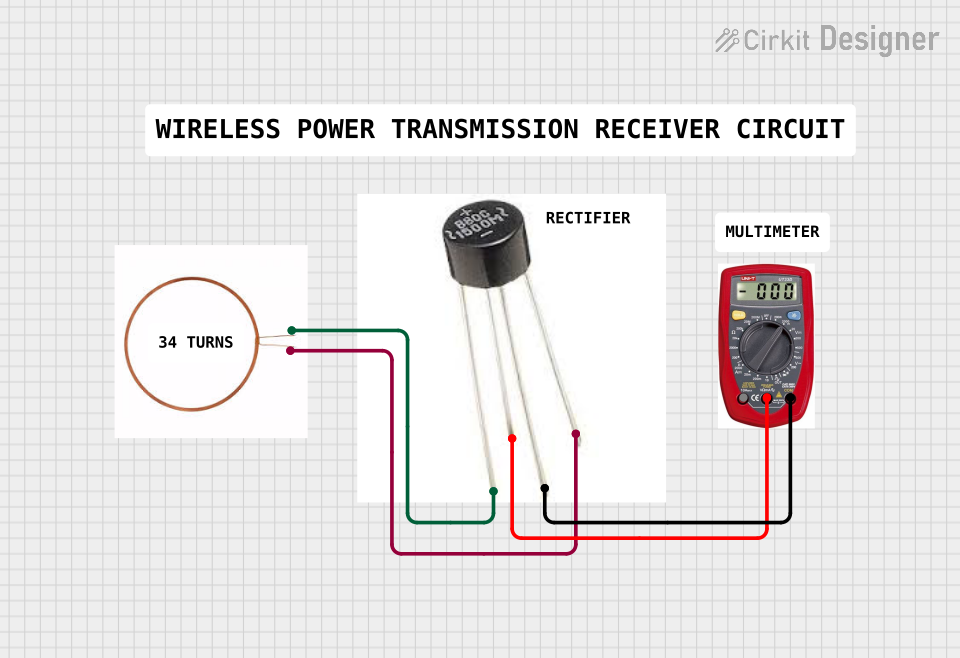
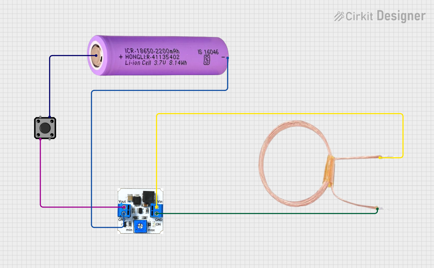
  • Q: Is it possible to use this coil for wireless charging?

    • A: Yes, but it must be part of a properly designed circuit for wireless power transfer.

Example Arduino UNO Code

Below is an example code snippet for using the 30-turn copper coil as part of an RLC circuit connected to an Arduino UNO for impedance measurement.

// Define the analog input pin where the coil is connected
const int coilPin = A0;

void setup() {
  // Initialize serial communication at 9600 bits per second
  Serial.begin(9600);
}

void loop() {
  // Read the voltage across the coil
  int sensorValue = analogRead(coilPin);
  
  // Convert the analog reading to voltage (assuming a 5V Arduino)
  float voltage = sensorValue * (5.0 / 1023.0);
  
  // Print out the voltage
  Serial.println(voltage);
  
  // Wait for a bit to avoid spamming the serial monitor
  delay(500);
}

Note: This code is a simple example to read and display the voltage across the coil. For actual impedance measurement, additional circuitry and calculations are required.