
How to Use LED Matrix - Serial Interface - Red/Green/Blue: Examples, Pinouts, and Specs
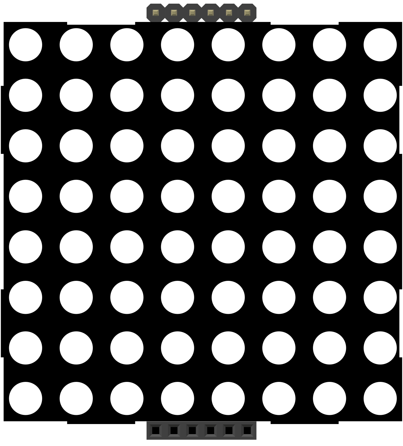
 Design with LED Matrix - Serial Interface - Red/Green/Blue in Cirkit Designer
Introduction
The LED Matrix - Serial Interface - Red/Green/Blue (Manufacturer Part ID: DEV-00760) by SparkFun Electronics is a versatile display component consisting of an array of LEDs capable of emitting red, green, and blue light. This allows for the creation of a wide range of colors and dynamic patterns. The matrix is controlled via a serial interface, making it easy to integrate with microcontrollers such as Arduino, Raspberry Pi, and other embedded systems.
Explore Projects Built with LED Matrix - Serial Interface - Red/Green/Blue
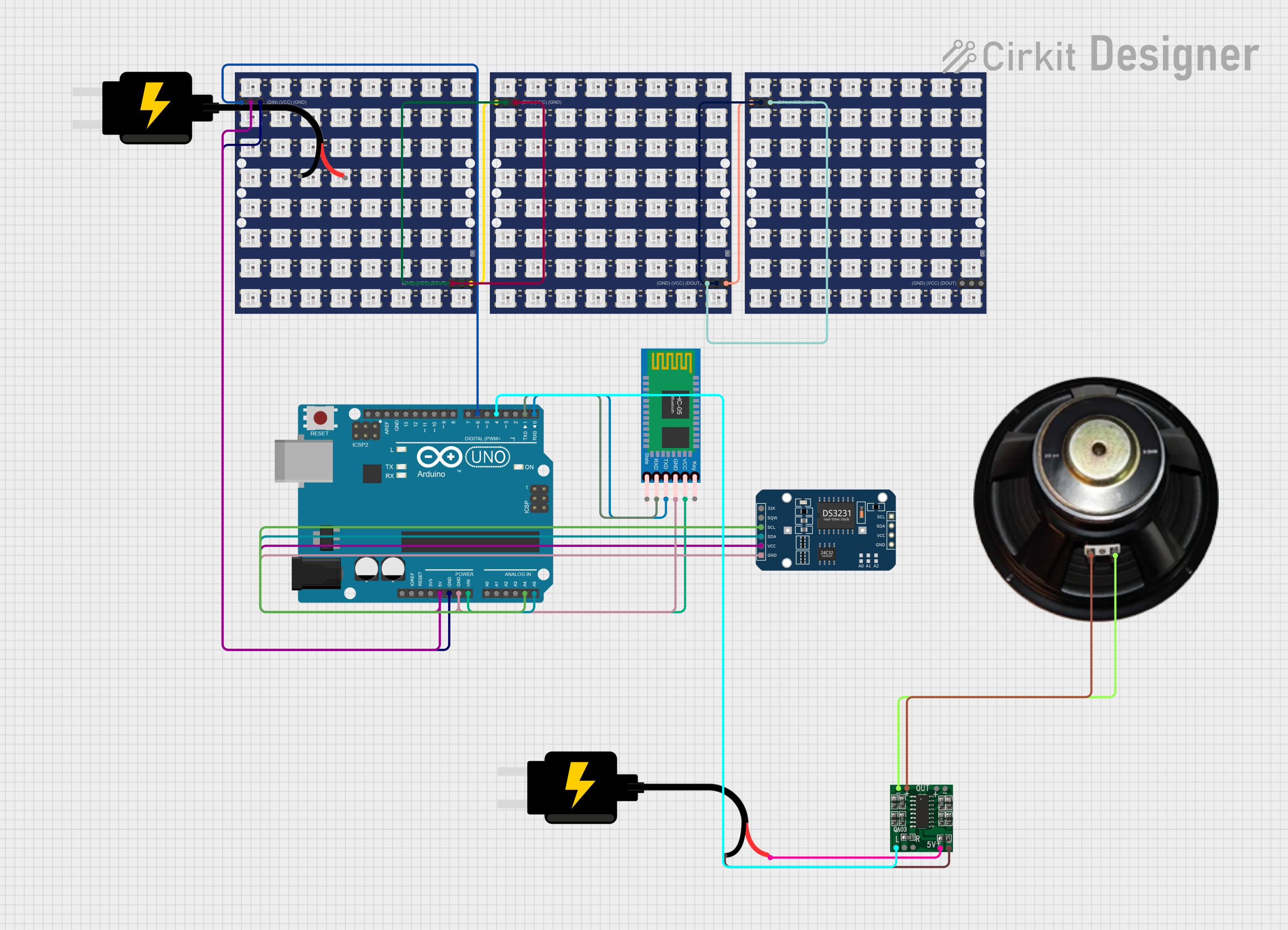 Open Project in Cirkit Designer
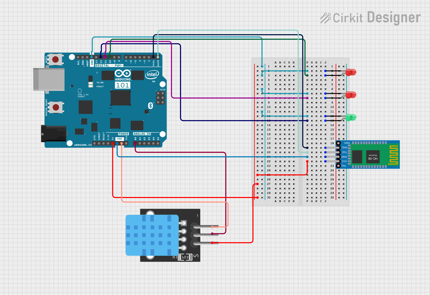 Open Project in Cirkit Designer
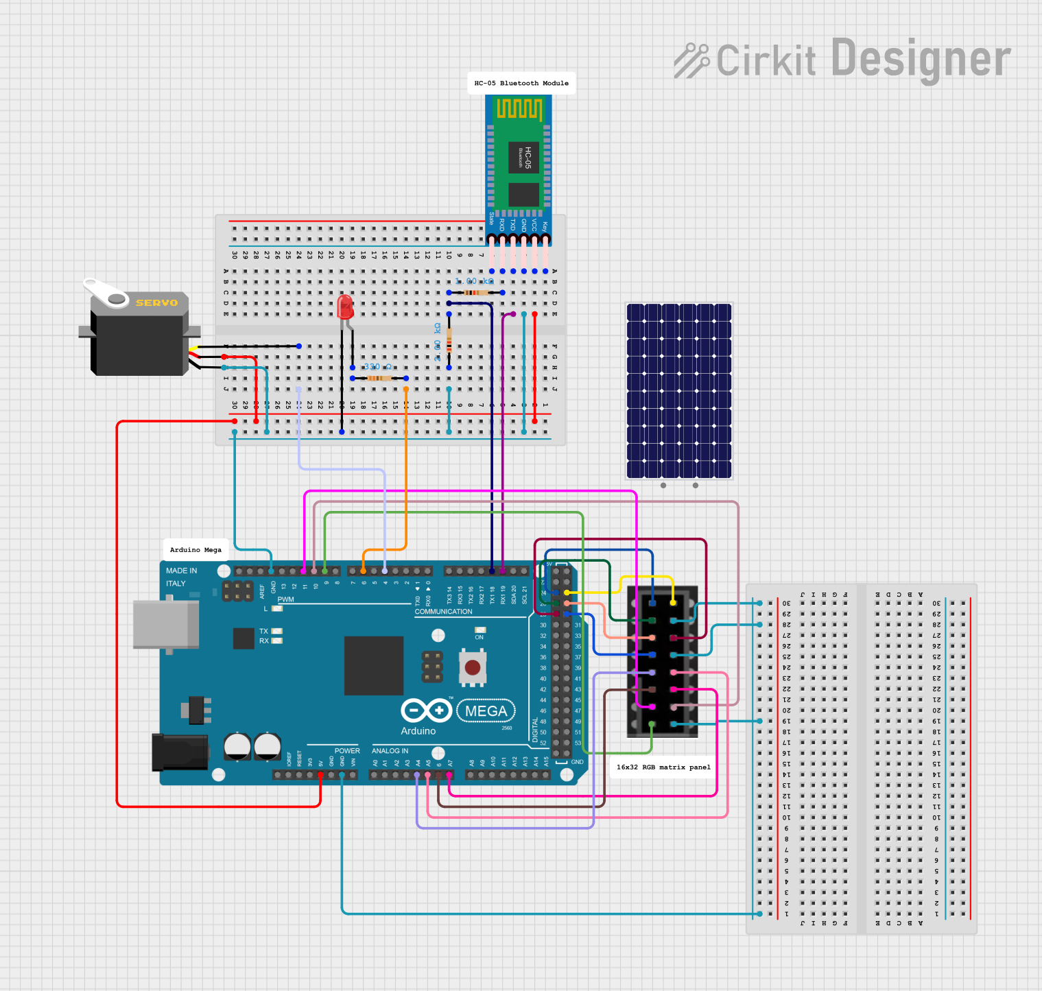 Open Project in Cirkit Designer
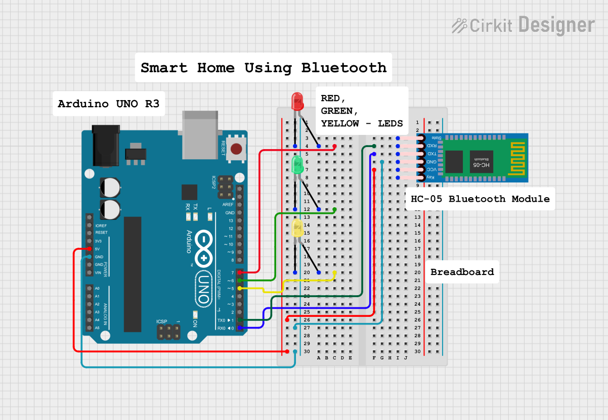 Open Project in Cirkit Designer
Explore Projects Built with LED Matrix - Serial Interface - Red/Green/Blue
Open Project in Cirkit DesignerOpen Project in Cirkit DesignerOpen Project in Cirkit DesignerOpen Project in Cirkit DesignerCommon Applications and Use Cases
- Digital Displays: Ideal for creating scrolling text, animations, or visual indicators.
- Wearable Electronics: Used in smart clothing or accessories for dynamic lighting effects.
- IoT Devices: Displays status updates or notifications in smart home or industrial systems.
- Educational Projects: A great tool for learning about LED control, serial communication, and color mixing.
- Art Installations: Enables creative lighting designs and interactive displays.
Technical Specifications
Key Technical Details
| Parameter | Value |
|---|---|
| Manufacturer | SparkFun Electronics |
| Part ID | DEV-00760 |
| LED Colors | Red, Green, Blue (RGB) |
| Communication Protocol | Serial Interface |
| Operating Voltage | 5V DC |
| Operating Current | 20mA per LED (typical) |
| Dimensions | 32x32 LED array (1024 LEDs total) |
| Pixel Pitch | 3mm |
| Refresh Rate | Up to 60Hz |
| Viewing Angle | 120° |
| Operating Temperature | -20°C to 70°C |
Pin Configuration and Descriptions
The LED matrix uses a standard serial interface with the following pin configuration:
| Pin Name | Pin Number | Description |
|---|---|---|
| VCC | 1 | Power supply input (5V DC) |
| GND | 2 | Ground connection |
| DIN | 3 | Serial data input |
| CLK | 4 | Clock signal input |
| LAT | 5 | Latch signal input |
| OE | 6 | Output enable (active low) |
Usage Instructions
How to Use the Component in a Circuit
- Power Supply: Connect the VCC pin to a 5V DC power source and the GND pin to ground.
- Data Connection: Use the DIN pin to send serial data to the matrix. This data determines which LEDs are lit and their colors.
- Clock Signal: Connect the CLK pin to a clock signal from your microcontroller to synchronize data transmission.
- Latch Signal: Use the LAT pin to latch the data into the matrix. This ensures the LEDs display the correct pattern.
- Output Enable: The OE pin controls whether the LEDs are active. Pull this pin low to enable the display.
Important Considerations and Best Practices
- Current Limiting: Ensure the power supply can handle the current requirements of the matrix. Use a regulated 5V DC source.
- Heat Management: Prolonged use at high brightness may generate heat. Ensure proper ventilation or heat dissipation.
- Serial Communication: Use a microcontroller with sufficient processing power to handle the data rate required for smooth animations.
- Wiring: Keep wiring short and secure to avoid signal degradation, especially for the clock and data lines.
Example Code for Arduino UNO
Below is an example of how to control the LED matrix using an Arduino UNO. This code uses the Adafruit_GFX and Adafruit_LEDBackpack libraries.
#include <Adafruit_GFX.h>         // Graphics library for LED matrix
#include <Adafruit_LEDBackpack.h> // Library for controlling LED matrices

Adafruit_BicolorMatrix matrix = Adafruit_BicolorMatrix();

void setup() {
  matrix.begin(0x70); // Initialize the matrix at I2C address 0x70
}

void loop() {
  matrix.clear(); // Clear the display

  // Draw a red pixel at (0, 0)
  matrix.drawPixel(0, 0, LED_RED);

  // Draw a green pixel at (1, 1)
  matrix.drawPixel(1, 1, LED_GREEN);

  // Draw a blue pixel at (2, 2)
  matrix.drawPixel(2, 2, LED_YELLOW); // Yellow is a mix of red and green

  matrix.writeDisplay(); // Update the display
  delay(500);            // Wait for 500ms
}
Note: Install the required libraries via the Arduino Library Manager before running the code.
Troubleshooting and FAQs
Common Issues and Solutions
LEDs Not Lighting Up:
- Cause: Incorrect wiring or insufficient power supply.
- Solution: Double-check all connections and ensure the power supply provides 5V DC with adequate current.
Flickering or Dim LEDs:
- Cause: Signal degradation or insufficient current.
- Solution: Use shorter wires for data and clock lines. Ensure the power supply can handle the current demand.
Incorrect Colors Displayed:
- Cause: Data corruption or incorrect timing.
- Solution: Verify the clock and data signals. Ensure the microcontroller's timing matches the matrix's requirements.
Matrix Not Responding to Commands:
- Cause: Incorrect I2C address or communication failure.
- Solution: Confirm the I2C address in the code matches the matrix's address. Check for loose connections.
FAQs
Q: Can I daisy-chain multiple LED matrices?
A: Yes, multiple matrices can be daisy-chained by connecting the DOUT pin of one matrix to the DIN pin of the next. Ensure the microcontroller can handle the increased data rate.
Q: What is the maximum refresh rate?
A: The matrix supports refresh rates up to 60Hz, depending on the microcontroller's processing power and the complexity of the display pattern.
Q: Can I power the matrix directly from the Arduino UNO?
A: No, the Arduino UNO cannot supply enough current for the matrix. Use an external 5V DC power supply.
Q: How do I create custom animations?
A: Use the Adafruit_GFX library to draw shapes, text, and patterns. Update the display in the loop() function to create animations.
This documentation provides a comprehensive guide to using the LED Matrix - Serial Interface - Red/Green/Blue. For further assistance, refer to the SparkFun Electronics website or community forums.