How to Use PZEM-004T: Examples, Pinouts, and Specs
Introduction
The PZEM-004T is a multifunctional energy meter designed for monitoring and measuring key parameters in AC circuits. It can measure voltage, current, power, energy, and frequency, making it a versatile tool for energy management and analysis. The module is equipped with a UART interface, enabling seamless communication with microcontrollers and computers for data logging and remote monitoring. Its compact design and high accuracy make it suitable for a wide range of applications.
Explore Projects Built with PZEM-004T


Explore Projects Built with PZEM-004T
Common Applications
- Home energy monitoring systems
- Industrial equipment power analysis
- Renewable energy systems (e.g., solar inverters)
- IoT-based energy management solutions
- Laboratory and educational projects
Technical Specifications
Key Specifications
| Parameter | Value |
|---|---|
| Voltage Range | 80V - 260V AC |
| Current Range | 0A - 100A (with external CT) |
| Power Range | 0W - 22kW |
| Energy Range | 0kWh - 9999kWh |
| Frequency Range | 45Hz - 65Hz |
| Communication | UART (9600 baud rate) |
| Power Supply | 5V DC (external) |
| Accuracy | ±0.5% |
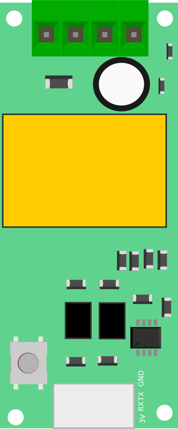
Pin Configuration
The PZEM-004T module has a 4-pin interface for communication and power. Below is the pinout description:
| Pin Number | Name | Description |
|---|---|---|
| 1 | VCC | 5V DC power supply input |
| 2 | GND | Ground connection |
| 3 | TX | UART Transmit pin (connects to RX of MCU) |
| 4 | RX | UART Receive pin (connects to TX of MCU) |
Additionally, the module includes terminals for connecting the AC input and the current transformer (CT) for current measurement.
Usage Instructions
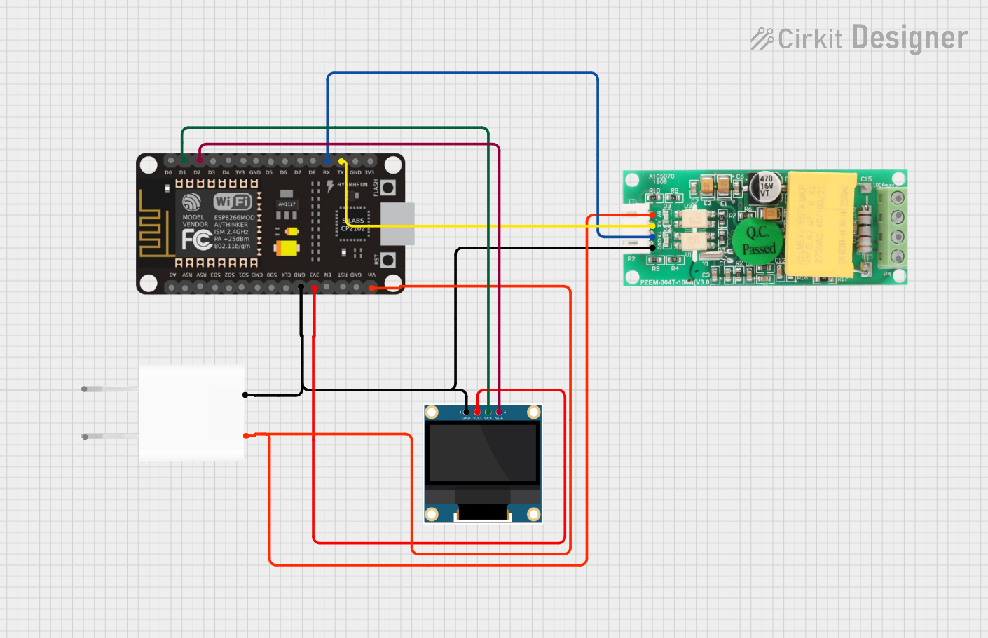
Connecting the PZEM-004T
- Power Supply: Connect the
VCCpin to a 5V DC power source and theGNDpin to ground. - UART Communication: Connect the
TXpin of the PZEM-004T to theRXpin of your microcontroller (e.g., Arduino), and theRXpin of the PZEM-004T to theTXpin of the microcontroller. - AC Input: Connect the AC live and neutral wires to the input terminals of the module.
- Current Transformer (CT): Place the CT around the live wire of the AC circuit to measure current.
Important Considerations
- Ensure the AC voltage and current do not exceed the module's rated limits.
- Use proper insulation and safety precautions when working with high-voltage AC circuits.
- The UART interface operates at 5V logic levels. Use a level shifter if interfacing with 3.3V devices.
- Avoid placing the CT around both live and neutral wires, as this will result in incorrect readings.
Example: Using PZEM-004T with Arduino UNO
Below is an example Arduino sketch to read data from the PZEM-004T module:
#include <SoftwareSerial.h>

// Define RX and TX pins for SoftwareSerial
SoftwareSerial pzemSerial(10, 11); // RX = pin 10, TX = pin 11

// PZEM-004T communication commands
byte readCommand[] = {0xB0, 0xC0, 0xA8, 0x01, 0x01, 0x00, 0x1A};

// Function to calculate checksum
byte calculateChecksum(byte *data, int length) {
  byte checksum = 0;
  for (int i = 0; i < length; i++) {
    checksum += data[i];
  }
  return ~checksum + 1;
}

void setup() {
  Serial.begin(9600);          // Initialize Serial Monitor
  pzemSerial.begin(9600);      // Initialize PZEM-004T communication
  Serial.println("PZEM-004T Test");
}

void loop() {
  // Send read command to PZEM-004T
  pzemSerial.write(readCommand, sizeof(readCommand));

  // Wait for response
  delay(100);

  // Read response from PZEM-004T
  byte response[7];
  int index = 0;
  while (pzemSerial.available() > 0 && index < 7) {
    response[index++] = pzemSerial.read();
  }

  // Validate response length
  if (index == 7) {
    // Extract voltage, current, and power from response
    float voltage = (response[0] << 8 | response[1]) / 10.0;
    float current = (response[2] << 8 | response[3]) / 100.0;
    float power = (response[4] << 8 | response[5]) / 10.0;

    // Print values to Serial Monitor
    Serial.print("Voltage: ");
    Serial.print(voltage);
    Serial.println(" V");

    Serial.print("Current: ");
    Serial.print(current);
    Serial.println(" A");

    Serial.print("Power: ");
    Serial.print(power);
    Serial.println(" W");
  } else {
    Serial.println("Error: Invalid response");
  }

  delay(1000); // Wait 1 second before next reading
}
Notes on the Code
- The
readCommandarray contains the command to request data from the PZEM-004T. - The response is parsed to extract voltage, current, and power values.
- Ensure the RX and TX pins in the code match your Arduino wiring.
Troubleshooting and FAQs
Common Issues
No Data Received:
- Ensure the UART connections (TX and RX) are correct.
- Verify the baud rate is set to 9600 in both the code and the module.
- Check the power supply to the module.
Incorrect Readings:
- Ensure the CT is properly clamped around the live wire only.
- Verify the AC input voltage is within the specified range (80V - 260V AC).
Module Not Responding:
- Check for loose connections or damaged wires.
- Ensure the module is not exposed to excessive heat or moisture.
FAQs
Q: Can the PZEM-004T measure DC circuits?
A: No, the PZEM-004T is designed specifically for AC circuits and cannot measure DC voltage or current.
Q: Can I use the PZEM-004T with a 3.3V microcontroller?
A: Yes, but you will need a level shifter to convert the UART signals to 3.3V logic levels.
Q: How do I reset the energy counter?
A: The energy counter can be reset by sending a specific UART command to the module. Refer to the module's datasheet for details.
Q: Can I extend the CT cable?
A: Yes, but ensure the extension does not introduce significant resistance or noise, which could affect accuracy. Use shielded cables if possible.