How to Use WS2812 RGB LED strip: Examples, Pinouts, and Specs
Introduction
The WS2812 RGB LED strip is a flexible and programmable lighting solution that features individually addressable RGB LEDs. Each LED on the strip can be controlled independently, allowing for a wide array of colors and animations. These strips are commonly used in decorative lighting, signage, and interactive art installations, as well as in DIY projects and commercial products that require dynamic lighting effects.
Explore Projects Built with WS2812 RGB LED strip
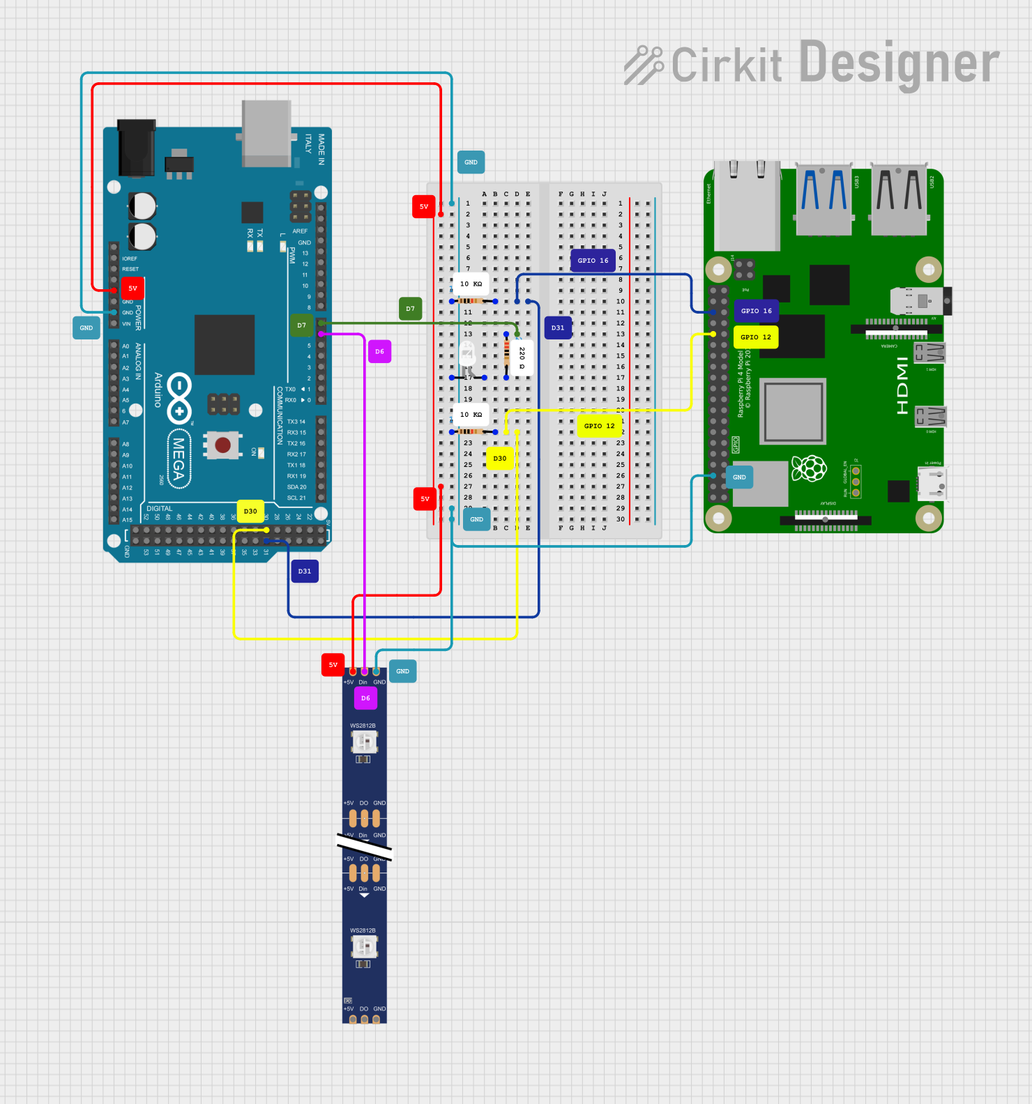
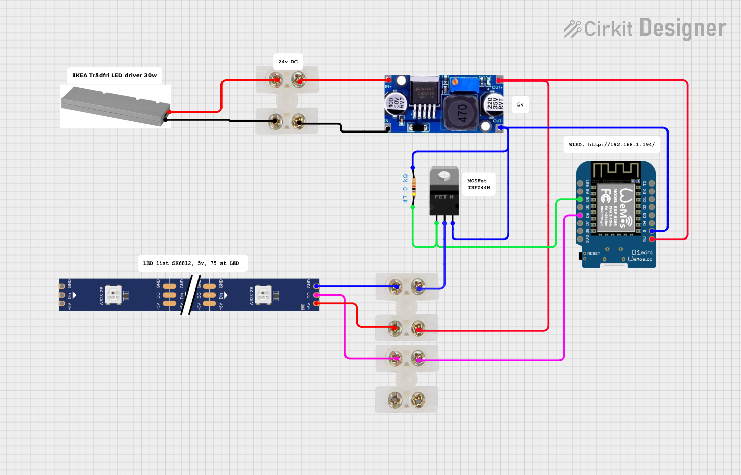
Explore Projects Built with WS2812 RGB LED strip
Technical Specifications
Key Technical Details
- Supply Voltage (Vcc): 5V DC
- Operating Current per LED: 50mA max (with full brightness white)
- LED Quantity: Varies by length (typically 30, 60, or 144 LEDs per meter)
- Communication Protocol: Single-wire, high-speed, custom protocol
- Color Depth: 24-bit color (8 bits per channel)
- Refresh Rate: ≥400 Hz
- Operating Temperature: -20°C to 60°C
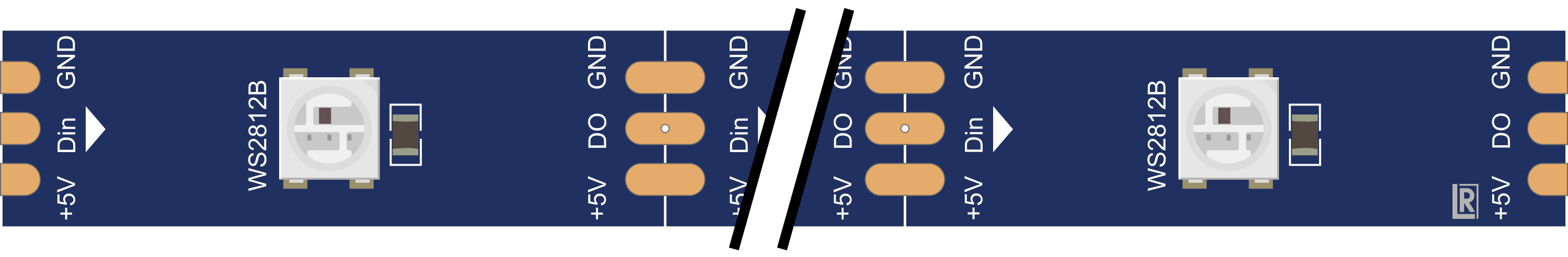
Pin Configuration and Descriptions
| Pin Name | Description |
|---|---|
| VDD | Power supply (5V DC) |
| GND | Ground connection |
| DIN | Data input from microcontroller |
| DOUT | Data output to next LED or LED strip |
Usage Instructions
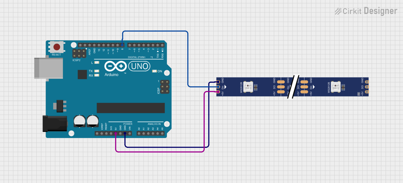
Connecting to a Circuit
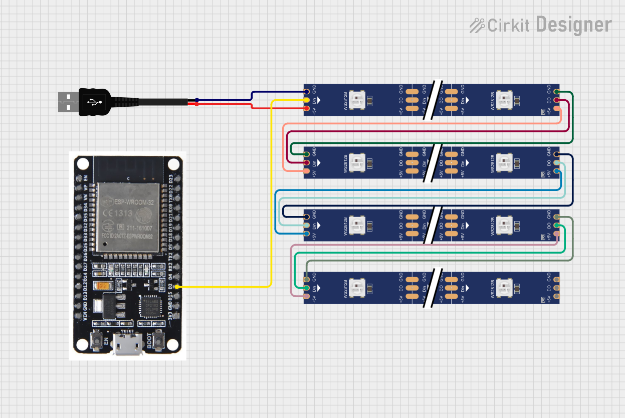
- Power Supply: Connect the VDD pin to a 5V power supply and the GND pin to the common ground. Ensure that the power supply can handle the current requirements of the entire strip.
- Data Signal: Connect the DIN pin to a digital output pin on your microcontroller (e.g., an Arduino UNO).
- Data Chaining: If connecting multiple strips or LEDs, connect the DOUT pin of the first LED to the DIN pin of the next.
Best Practices
- Use a capacitor (e.g., 1000 µF, 6.3V) across the power supply pins to prevent initial onrush of current from damaging the LEDs.
- Add a series resistor (e.g., 330Ω) on the data input line to reduce noise on the data signal.
- Ensure that the ground of the LED strip is connected to the ground of the microcontroller to avoid potential control issues.
- Avoid running the LEDs at full brightness for extended periods to prevent overheating and extend their lifespan.
Example Code for Arduino UNO
#include <Adafruit_NeoPixel.h>

#define LED_PIN     6 // Digital output pin connected to the strip
#define LED_COUNT  30 // Number of LEDs in the strip

// Initialize the strip
Adafruit_NeoPixel strip(LED_COUNT, LED_PIN, NEO_GRB + NEO_KHZ800);

void setup() {
  strip.begin();           // Initialize the strip
  strip.show();            // Initialize all pixels to 'off'
}

void loop() {
  // Set the first pixel to red color (R, G, B)
  strip.setPixelColor(0, strip.Color(255, 0, 0));
  strip.show(); // Update the strip with the color data
  delay(500); // Wait for half a second

  // Turn off the first pixel
  strip.setPixelColor(0, strip.Color(0, 0, 0));
  strip.show();
  delay(500);
}
Troubleshooting and FAQs
Common Issues
- LEDs not lighting up: Check power supply connections and ensure the data input pin is correctly connected to the microcontroller.
- Incorrect colors: Verify that the data signal is not degraded due to long wires or insufficient voltage levels.
- Flickering LEDs: Ensure that there is a common ground between the LED strip and the microcontroller. Also, check for any loose connections.
FAQs
Q: Can I cut the LED strip to a custom length? A: Yes, the strip can be cut at designated points, usually marked with a line and a pair of copper pads.
Q: How do I control multiple LED strips? A: Multiple strips can be chained by connecting the DOUT of one strip to the DIN of the next. Ensure that your microcontroller can handle the increased data processing.
Q: What is the maximum length of the strip I can control? A: The maximum length depends on the power supply capacity and the ability of the microcontroller to process the data for all LEDs. Signal amplifiers and separate power injection may be required for very long strips.
Q: How do I prevent voltage drop along the strip? A: For longer strips, it's recommended to provide power at both ends of the strip or at multiple points along the strip to prevent voltage drop and color inconsistencies.