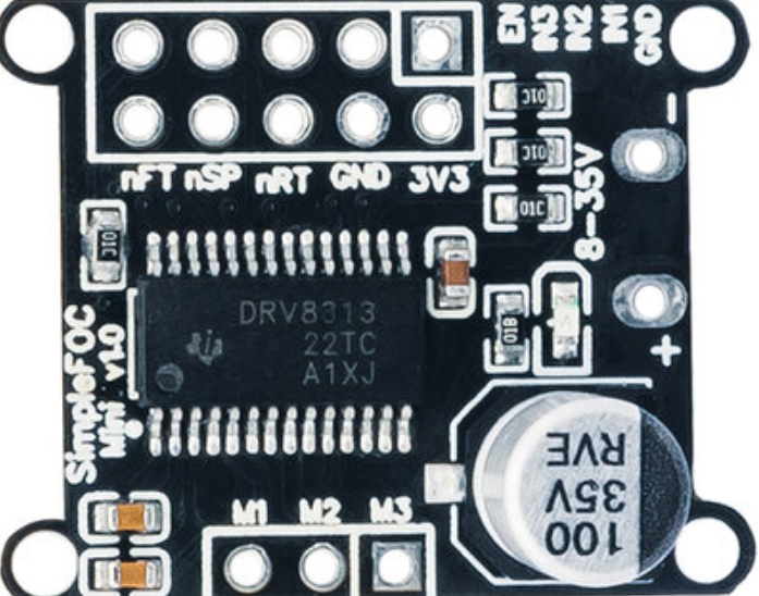
The SimpleFOC Mini is a compact and efficient motor control board designed for driving brushless DC (BLDC) motors using advanced field-oriented control (FOC) techniques. This board is ideal for applications requiring precise motor control, such as robotics, automation, gimbals, and small electric vehicles. Its small form factor and robust design make it a versatile choice for both hobbyists and professionals.
Common applications include:
Robotics (e.g., robotic arms, mobile robots)
Gimbal stabilization systems
Small electric vehicles
Automation systems requiring precise motor control
Explore Projects Built with SimpleFOC mini
Use Cirkit Designer to design, explore, and prototype these projects online. Some projects support real-time simulation. Click "Open Project" to start designing instantly!
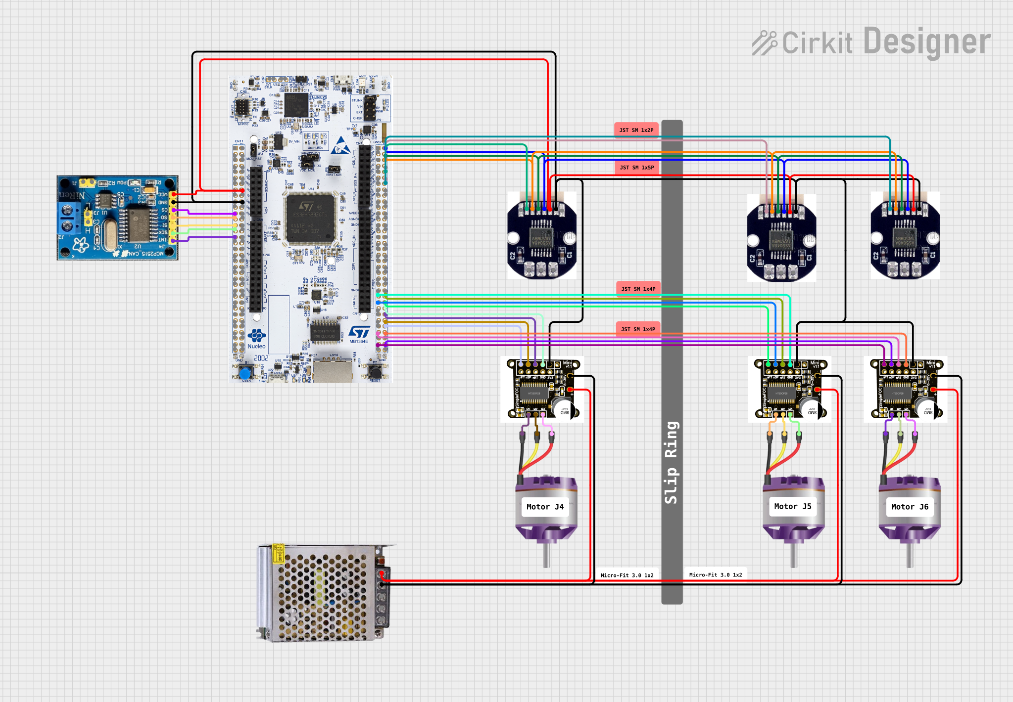
This is a motor control system designed to operate and manage multiple brushless motors with feedback from magnetic encoders. It uses a STM32H7 microcontroller for control logic, SimpleFOCMini drivers for motor control, and a CAN BUS for communication, all powered by a 12V DC supply.
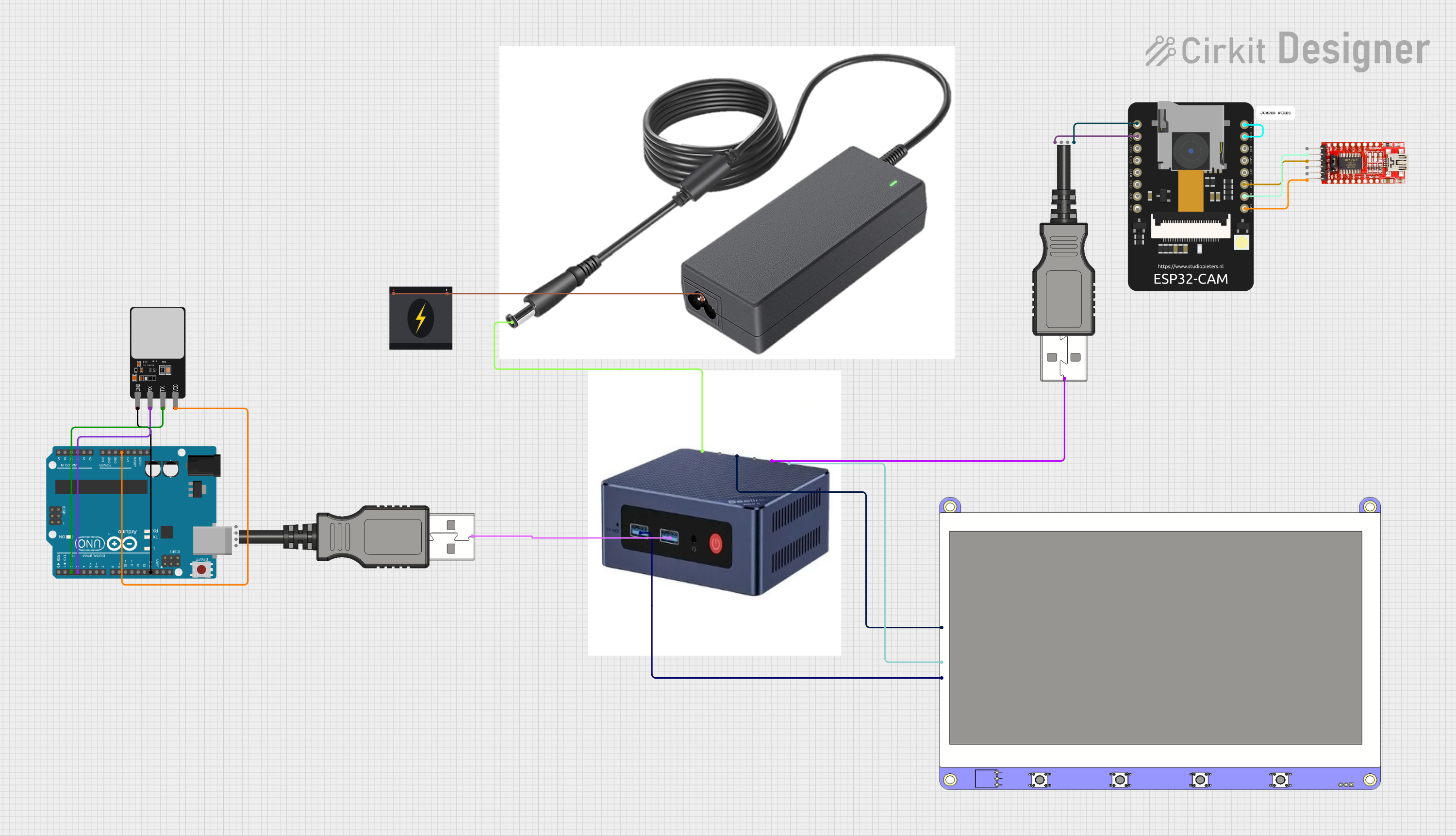
This circuit features a Beelink MINI S12 N95 computer connected to a 7-inch display via HDMI for video output and two USB connections for power and touch screen functionality. An Arduino UNO is interfaced with a fingerprint scanner for biometric input. The Beelink MINI S12 N95 is powered by a PC power supply, which in turn is connected to a 240V power source. Additionally, an ESP32 CAM module is powered and programmed via a USB plug and an FTDI programmer, respectively, for wireless camera capabilities.
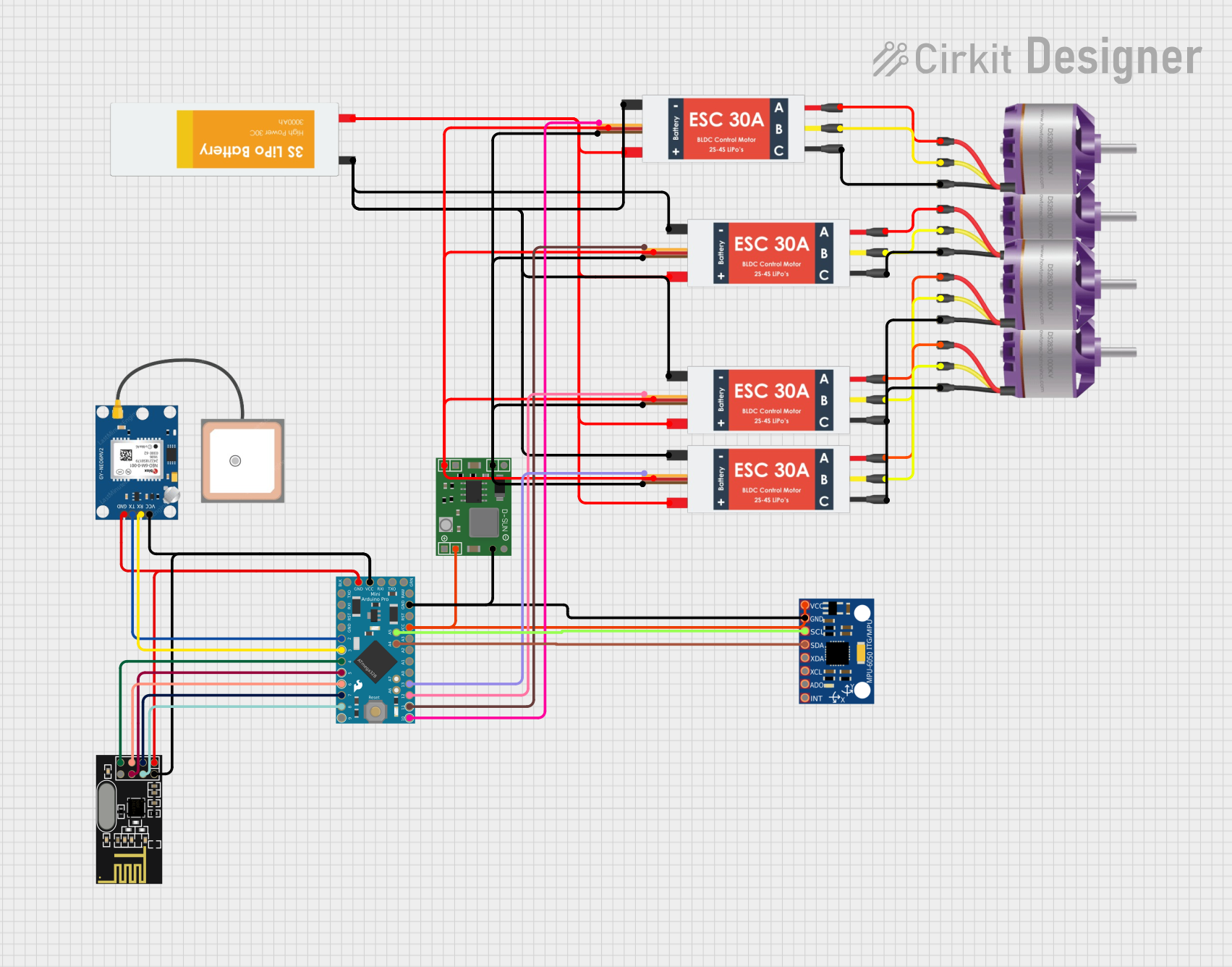
This circuit is designed for a quadcopter control system. It features an Arduino Pro Mini as the central microcontroller, interfacing with a GPS module for positioning, an NRF24L01 module for wireless communication, and an MPU-6050 for motion sensing. Power regulation is managed by an MP1584EN board, and four electronic speed controllers (ESCs) are connected to brushless motors for propeller control.
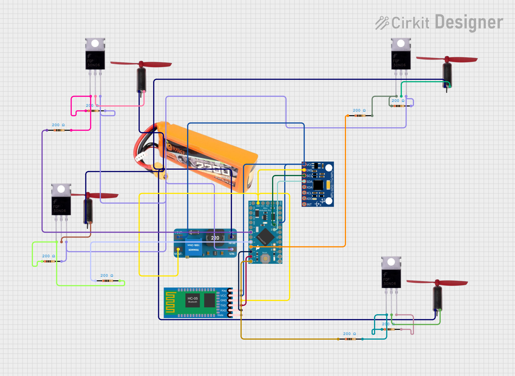
This is a motion-controlled device with wireless capabilities, powered by a LiPo battery with voltage regulation. It uses an Arduino Pro Mini to process MPU-6050 sensor data and control coreless motors via MOSFETs, interfacing with an external device through an HC-05 Bluetooth module.
The SimpleFOC Mini is designed to provide reliable and efficient motor control. Below are its key technical specifications:
Parameter
Value
Input Voltage Range
6V to 25V
Continuous Current
Up to 5A
Peak Current
10A (short duration)
Motor Type Supported
Brushless DC (BLDC) motors
Control Algorithm
Field-Oriented Control (FOC)
Communication Interfaces
UART, I2C, SPI
Dimensions
25mm x 25mm
Weight
5g
Pin Configuration and Descriptions
The SimpleFOC Mini features a straightforward pin layout for easy integration into your projects. Below is the pin configuration:
Pin Name
Type
Description
VIN
Power Input
Main power input (6V to 25V) for the motor driver.
GND
Ground
Common ground for power and signal connections.
MOTOR_A
Motor Output
Connection to phase A of the BLDC motor.
MOTOR_B
Motor Output
Connection to phase B of the BLDC motor.
MOTOR_C
Motor Output
Connection to phase C of the BLDC motor.
EN
Digital Input
Enable pin to activate the motor driver.
PWM1
PWM Input
PWM signal input for motor control.
PWM2
PWM Input
Optional second PWM input for advanced control.
UART_TX
UART Output
Transmit pin for UART communication.
UART_RX
UART Input
Receive pin for UART communication.
I2C_SCL
I2C Clock
Clock line for I2C communication.
I2C_SDA
I2C Data
Data line for I2C communication.
SPI_MOSI
SPI Input
Master Out Slave In for SPI communication.
SPI_MISO
SPI Output
Master In Slave Out for SPI communication.
SPI_SCK
SPI Clock
Clock line for SPI communication.
SPI_CS
SPI Chip Select
Chip select for SPI communication.
Usage Instructions
How to Use the SimpleFOC Mini in a Circuit
Power Supply: Connect a power source (6V to 25V) to the VIN and GND pins. Ensure the power supply can handle the current requirements of your motor.
Motor Connection: Connect the three phases of your BLDC motor to the MOTOR_A, MOTOR_B, and MOTOR_C pins.
Control Signal: Use either PWM, UART, I2C, or SPI to send control signals to the board. For basic setups, PWM is the easiest to use.
Enable the Driver: Pull the EN pin high to enable the motor driver.
Programming: If using an Arduino UNO, connect the communication pins (e.g., UART or I2C) to the corresponding pins on the Arduino.
Important Considerations and Best Practices
Heat Dissipation: The board can handle up to 5A continuously, but ensure proper ventilation or a heatsink for high-current applications.
Motor Compatibility: Ensure your BLDC motor is compatible with the voltage and current ratings of the SimpleFOC Mini.
Signal Integrity: Use short and shielded wires for communication signals to minimize noise.
Power Supply: Use a stable and noise-free power supply to avoid erratic motor behavior.
Example Code for Arduino UNO
Below is an example of how to control a BLDC motor using the SimpleFOC Mini with an Arduino UNO:
#include <SimpleFOC.h> // Include the SimpleFOC library

// Define motor and driver objects
BLDCMotor motor = BLDCMotor(7); // Motor with 7 pole pairs
BLDCDriver3PWM driver = BLDCDriver3PWM(9, 10, 11); // PWM pins for motor phases

void setup() {
  // Initialize driver
  driver.voltage_power_supply = 12; // Set power supply voltage
  driver.init();
  motor.linkDriver(&driver);

  // Set motor parameters
  motor.voltage_limit = 6; // Limit motor voltage
  motor.controller = MotionControlType::velocity; // Velocity control mode

  // Initialize motor
  motor.init();
  Serial.begin(115200); // Start serial communication
  Serial.println("Motor ready!");
}

void loop() {
  // Set motor velocity (e.g., 2 rad/s)
  motor.move(2);
}
Note: Install the SimpleFOC library in your Arduino IDE before uploading the code.
Troubleshooting and FAQs
Common Issues and Solutions
Motor Not Spinning:
Ensure the EN pin is pulled high.
Verify the motor connections (MOTOR_A, MOTOR_B, MOTOR_C).
Check the power supply voltage and current ratings.
Overheating:
Reduce the motor load or current limit.
Improve ventilation or add a heatsink to the board.
Erratic Motor Behavior:
Check for noise in the power supply or signal lines.
Ensure proper grounding and short signal wires.
Communication Issues:
Verify the baud rate for UART communication.
Check the wiring for I2C or SPI connections.
FAQs
Can I use the SimpleFOC Mini with a stepper motor?
No, the SimpleFOC Mini is designed specifically for BLDC motors.
What is the maximum motor speed supported?
The maximum speed depends on the motor's specifications and the control algorithm but is typically limited by the board's processing speed and power supply.
Can I use a battery as the power source?
Yes, as long as the battery voltage is within the 6V to 25V range and can supply sufficient current.
Is the board compatible with other microcontrollers?
Yes, the SimpleFOC Mini can be used with various microcontrollers, including STM32, ESP32, and Arduino boards.

 Open Project in Cirkit Designer