Cirkit Designer Logo
Cirkit Designer
Your all-in-one circuit design IDE
Home / 
Component Documentation

How to Use Adafruit 2.9 inch eInk Display Breakout: Examples, Pinouts, and Specs

Image of Adafruit 2.9 inch eInk Display Breakout
Cirkit Designer LogoDesign with Adafruit 2.9 inch eInk Display Breakout in Cirkit Designer

Introduction

The Adafruit 2.9 inch eInk Display Breakout is a versatile and energy-efficient display module that provides a crisp black and white visual output. eInk displays, also known as ePaper displays, mimic the appearance of ink on paper, which makes them highly readable even in direct sunlight. This display is particularly suitable for applications where power consumption is critical, as it only uses power when updating the display content.

Common applications include:

  • E-readers
  • Electronic shelf labels
  • Wearable devices
  • Digital signage
  • Low-power time displays

Explore Projects Built with Adafruit 2.9 inch eInk Display Breakout

Use Cirkit Designer to design, explore, and prototype these projects online. Some projects support real-time simulation. Click "Open Project" to start designing instantly!
Arduino 101 OLED Display Animation Project
Image of wokwi animater test: A project utilizing Adafruit 2.9 inch eInk Display Breakout in a practical application
This circuit consists of an Arduino 101 microcontroller connected to a 0.96" OLED display via I2C communication. The Arduino runs a program that initializes the OLED and continuously displays an animated sequence of frames on the screen.
Cirkit Designer LogoOpen Project in Cirkit Designer
Arduino UNO-Based OLED Display with Dual Pushbutton Control
Image of pong game: A project utilizing Adafruit 2.9 inch eInk Display Breakout in a practical application
This circuit features an Arduino UNO microcontroller interfaced with a 0.96" OLED display and two pushbuttons. The OLED display is connected to the Arduino via the I2C protocol (SCK to A5 and SDA to A4), while the pushbuttons are connected to digital pins D2 and D3 for user input. The setup is likely intended for a simple interactive display application.
Cirkit Designer LogoOpen Project in Cirkit Designer
ESP32-Powered NTP Clock with Multiple GC9A01 Displays
Image of InfoOrbsFork: A project utilizing Adafruit 2.9 inch eInk Display Breakout in a practical application
This circuit features an ESP32 microcontroller connected to multiple GC9A01 displays and a USB Type C breakout for power. The ESP32 runs a sketch to retrieve the current time from an NTP server over WiFi and displays the hours and minutes across the GC9A01 displays, with each display showing a single digit or colon separator. Pushbuttons are connected to GPIOs on the ESP32, potentially for user input to control display functions or settings.
Cirkit Designer LogoOpen Project in Cirkit Designer
ESP32 Devkit V1 and OLED Display Bitmap Viewer
Image of Esp32_monochromeimage: A project utilizing Adafruit 2.9 inch eInk Display Breakout in a practical application
This circuit consists of an ESP32 Devkit V1 microcontroller connected to a 1.3" OLED display via I2C communication. The ESP32 initializes the OLED display and renders a predefined bitmap image on it.
Cirkit Designer LogoOpen Project in Cirkit Designer

Explore Projects Built with Adafruit 2.9 inch eInk Display Breakout

Use Cirkit Designer to design, explore, and prototype these projects online. Some projects support real-time simulation. Click "Open Project" to start designing instantly!
Image of wokwi animater test: A project utilizing Adafruit 2.9 inch eInk Display Breakout in a practical application
Arduino 101 OLED Display Animation Project
This circuit consists of an Arduino 101 microcontroller connected to a 0.96" OLED display via I2C communication. The Arduino runs a program that initializes the OLED and continuously displays an animated sequence of frames on the screen.
Cirkit Designer LogoOpen Project in Cirkit Designer
Image of pong game: A project utilizing Adafruit 2.9 inch eInk Display Breakout in a practical application
Arduino UNO-Based OLED Display with Dual Pushbutton Control
This circuit features an Arduino UNO microcontroller interfaced with a 0.96" OLED display and two pushbuttons. The OLED display is connected to the Arduino via the I2C protocol (SCK to A5 and SDA to A4), while the pushbuttons are connected to digital pins D2 and D3 for user input. The setup is likely intended for a simple interactive display application.
Cirkit Designer LogoOpen Project in Cirkit Designer
Image of InfoOrbsFork: A project utilizing Adafruit 2.9 inch eInk Display Breakout in a practical application
ESP32-Powered NTP Clock with Multiple GC9A01 Displays
This circuit features an ESP32 microcontroller connected to multiple GC9A01 displays and a USB Type C breakout for power. The ESP32 runs a sketch to retrieve the current time from an NTP server over WiFi and displays the hours and minutes across the GC9A01 displays, with each display showing a single digit or colon separator. Pushbuttons are connected to GPIOs on the ESP32, potentially for user input to control display functions or settings.
Cirkit Designer LogoOpen Project in Cirkit Designer
Image of Esp32_monochromeimage: A project utilizing Adafruit 2.9 inch eInk Display Breakout in a practical application
ESP32 Devkit V1 and OLED Display Bitmap Viewer
This circuit consists of an ESP32 Devkit V1 microcontroller connected to a 1.3" OLED display via I2C communication. The ESP32 initializes the OLED display and renders a predefined bitmap image on it.
Cirkit Designer LogoOpen Project in Cirkit Designer

Technical Specifications

Key Technical Details

  • Display Size: 2.9 inches
  • Resolution: 296 x 128 pixels
  • Display Color: Black and White
  • Operating Voltage: 3.3V
  • Interface: SPI
  • Partial Refresh Rate: < 1 second
  • Full Refresh Time: 2-3 seconds
  • Dimensions: 89mm x 38mm x 1mm

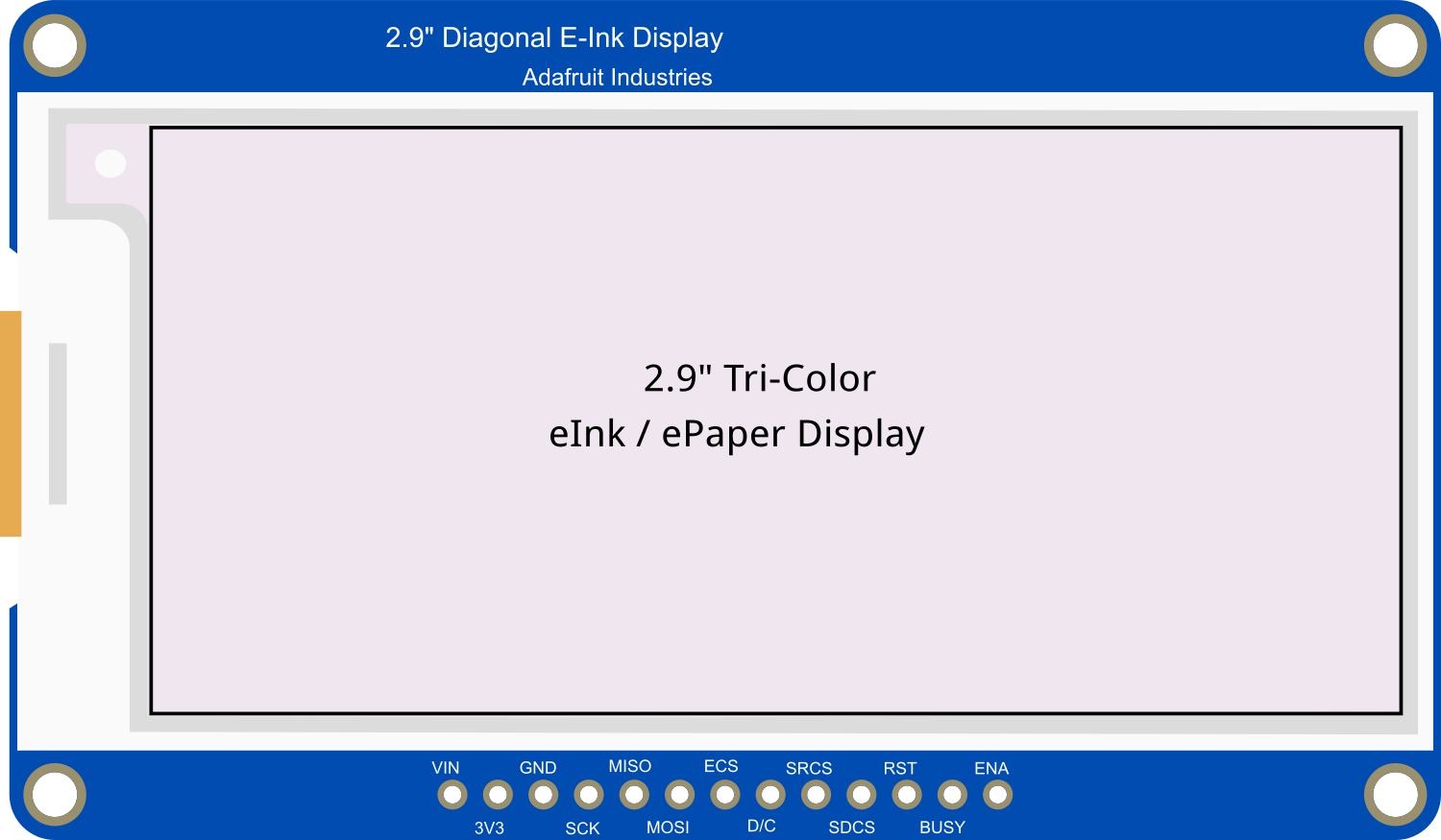
Pin Configuration and Descriptions

Pin Number Name Description
1 GND Ground connection
2 3V3 3.3V power supply input
3 BUSY Busy state output. High = busy, Low = ready
4 RST Reset pin. Active low
5 D/C Data/Command control pin
6 CS Chip Select for SPI
7 CLK SPI Clock
8 DIN SPI Data In (MOSI)
9 - Not connected
10 - Not connected

Usage Instructions

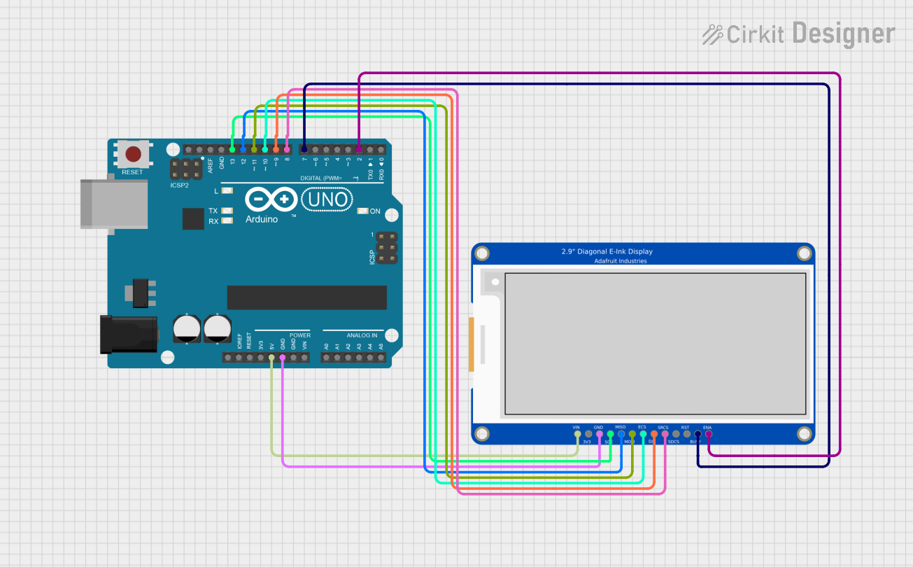
Integration with a Circuit

To use the Adafruit 2.9 inch eInk Display Breakout in a circuit:

  1. Connect the display's power pins (GND and 3V3) to your power source.
  2. Interface the display with a microcontroller (e.g., Arduino UNO) using the SPI pins (CS, CLK, DIN).
  3. The BUSY pin should be connected to a digital I/O pin on the microcontroller to read the display's status.
  4. The RST and D/C pins also connect to digital I/O pins for control purposes.

Best Practices

  • Avoid frequent full refreshes to maintain the longevity of the display.
  • Use partial refreshes for updating small sections of the display.
  • Ensure that the power supply is stable and within the specified voltage range.
  • Keep the display away from extreme temperatures and direct sunlight for extended periods.

Example Code for Arduino UNO

#include <Adafruit_GFX.h>
#include <Adafruit_EPD.h>

#define EPD_CS     10
#define EPD_DC     9
#define EPD_RESET  8
#define EPD_BUSY   7

// Create an instance of the display
Adafruit_SSD1675 display = Adafruit_SSD1675(296, 128, EPD_DC, EPD_RESET, EPD_CS, EPD_BUSY);

void setup() {
  display.begin(); // Initialize the display
  display.clearBuffer(); // Clear the buffer
  display.display(); // Refresh the display to clear any artifacts
  display.setTextSize(1); // Set the text size
  display.setTextColor(EPD_BLACK); // Set the text color
}

void loop() {
  display.setCursor(0, 0); // Set the cursor position
  display.print("Hello, eInk!"); // Print text to the buffer
  display.display(); // Update the display with the buffer content
  delay(2000); // Wait for 2 seconds
}

Ensure that the Adafruit GFX and EPD libraries are installed in your Arduino IDE before uploading this code to your Arduino UNO.

Troubleshooting and FAQs

Common Issues

  • Display not updating: Ensure that the display is correctly wired to the microcontroller and that the power supply is within the required voltage range.
  • Partial updates look corrupted: Partial refreshes can sometimes leave ghosting artifacts. Try a full refresh if the display becomes difficult to read.
  • Display is unresponsive: Check the BUSY pin status to ensure the display is not in a busy state. Also, verify that the RST pin is correctly wired and functioning.

FAQs

Q: Can the display show images? A: Yes, the display can show images in black and white. You will need to convert your images to a bitmap format compatible with the Adafruit GFX library.

Q: How long does the display retain the image after power is removed? A: The eInk display will retain the last image shown indefinitely without power.

Q: Is the display readable in the dark? A: No, unlike traditional backlit displays, eInk displays require external light to be readable, similar to paper.

Q: Can I use this display with a 5V microcontroller? A: While the display operates at 3.3V, level shifters can be used to interface with 5V logic. However, it is essential to ensure that the power supply to the display is 3.3V.

For further assistance, consult the Adafruit forums or the product's official support page.