How to Use PZEM 004-T: Examples, Pinouts, and Specs
Introduction
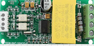
The PZEM 004-T is a multifunctional energy meter designed for monitoring and managing electrical consumption in AC circuits. It is capable of measuring key electrical parameters such as voltage, current, power, energy, frequency, and power factor. This compact and versatile module is widely used in applications like home automation, industrial energy monitoring, and power management systems. Its ability to interface with microcontrollers like Arduino makes it a popular choice for DIY projects and professional setups alike.
Explore Projects Built with PZEM 004-T


Explore Projects Built with PZEM 004-T
Technical Specifications
The PZEM 004-T offers precise measurements and supports communication via UART (serial interface), making it easy to integrate into various systems. Below are the key technical details:
General Specifications
| Parameter | Value |
|---|---|
| Operating Voltage | 80V - 260V AC |
| Measurable Voltage | 80V - 260V AC |
| Measurable Current | 0A - 100A (with external CT) |
| Power Measurement | 0W - 22kW |
| Energy Measurement | 0kWh - 9999kWh |
| Frequency Range | 45Hz - 65Hz |
| Power Factor Range | 0.00 - 1.00 |
| Communication | UART (9600 baud rate) |
| Dimensions | 70mm x 40mm x 30mm |
Pin Configuration
The PZEM 004-T module has a 4-pin interface for communication and power. Below is the pin configuration:
| Pin Number | Pin Name | Description |
|---|---|---|
| 1 | VCC | Power supply input (5V DC) |
| 2 | GND | Ground |
| 3 | RX | UART Receive pin (connect to TX of MCU) |
| 4 | TX | UART Transmit pin (connect to RX of MCU) |
Additionally, the module includes terminals for connecting the AC input and the current transformer (CT) for current measurement.
Usage Instructions
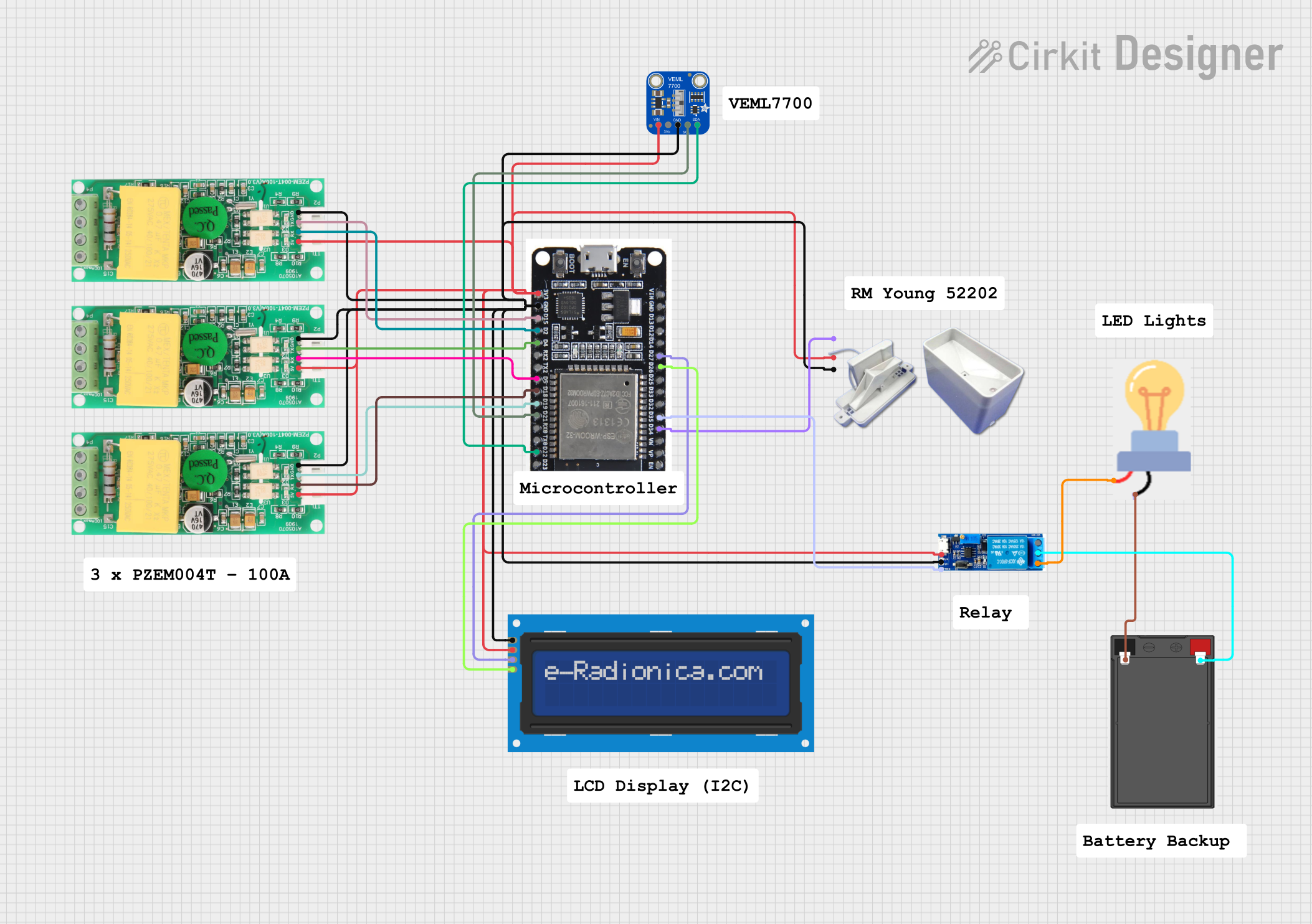
Connecting the PZEM 004-T
- Power Supply: Connect the VCC pin to a 5V DC power source and the GND pin to ground.
- UART Communication: Connect the RX pin of the PZEM 004-T to the TX pin of your microcontroller (e.g., Arduino), and the TX pin of the PZEM 004-T to the RX pin of the microcontroller.
- AC Input: Connect the AC live and neutral wires to the input terminals of the module.
- Current Transformer (CT): Place the CT around the live wire of the AC circuit to measure current.
Important Considerations
- Ensure that the AC input voltage is within the specified range (80V - 260V AC).
- The current transformer should only be placed around the live wire, not both live and neutral wires.
- Use proper insulation and safety precautions when working with high-voltage AC circuits.
- Avoid reversing the RX and TX connections, as this will prevent communication with the microcontroller.
Example: Using PZEM 004-T with Arduino UNO
Below is an example Arduino sketch to read data from the PZEM 004-T module using the SoftwareSerial library:
#include <SoftwareSerial.h>

// Define RX and TX pins for SoftwareSerial
#define RX_PIN 10  // Connect to TX of PZEM 004-T
#define TX_PIN 11  // Connect to RX of PZEM 004-T

SoftwareSerial pzemSerial(RX_PIN, TX_PIN);

void setup() {
  Serial.begin(9600);          // Initialize Serial Monitor
  pzemSerial.begin(9600);      // Initialize communication with PZEM 004-T
  Serial.println("PZEM 004-T Test");
}

void loop() {
  // Request data from PZEM 004-T
  byte request[] = {0xB0, 0xC0, 0xA8, 0x01, 0x01, 0x01, 0x00, 0x1A};
  pzemSerial.write(request, sizeof(request));

  delay(100);  // Wait for response

  // Read response from PZEM 004-T
  if (pzemSerial.available()) {
    Serial.print("Data received: ");
    while (pzemSerial.available()) {
      byte data = pzemSerial.read();
      Serial.print(data, HEX);
      Serial.print(" ");
    }
    Serial.println();
  }

  delay(1000);  // Wait before next request
}
Notes:
- The above code sends a sample request to the PZEM 004-T and prints the received data in hexadecimal format.
- For detailed data parsing and advanced functionality, use a dedicated library like the PZEM004T library available in the Arduino IDE Library Manager.
Troubleshooting and FAQs
Common Issues
No Data Received:
- Ensure the RX and TX connections are correct.
- Verify that the baud rate is set to 9600 in both the code and the module.
- Check the power supply to the module.
Incorrect Measurements:
- Ensure the current transformer is properly placed around the live wire.
- Verify that the AC input voltage is within the specified range.
Module Not Responding:
- Check for loose connections or damaged wires.
- Reset the module by disconnecting and reconnecting the power supply.
FAQs
Q: Can the PZEM 004-T measure DC voltage or current?
A: No, the PZEM 004-T is designed specifically for AC circuits and cannot measure DC parameters.
Q: What is the maximum current the module can measure?
A: The module can measure up to 100A using the provided current transformer.
Q: Can I use multiple PZEM 004-T modules with a single microcontroller?
A: Yes, you can use multiple modules by assigning unique addresses to each module and connecting them to different UART ports or using a multiplexer.
Q: Is the PZEM 004-T safe to use with high-voltage circuits?
A: Yes, but always follow proper safety precautions and ensure all connections are insulated to prevent electrical hazards.
By following this documentation, you can effectively integrate and use the PZEM 004-T module in your projects for accurate energy monitoring and management.