How to Use Air quality sensor: Examples, Pinouts, and Specs
Introduction
An air quality sensor is an electronic device designed to detect and measure the presence and concentration of various pollutants and harmful substances in the air. These sensors are vital for monitoring the air quality in both indoor and outdoor environments, providing data that can be used to assess the health and safety of the surrounding area. Common applications include home air quality monitoring, industrial emission control, environmental monitoring, and integration into HVAC systems to improve air circulation and filtration.
Explore Projects Built with Air quality sensor
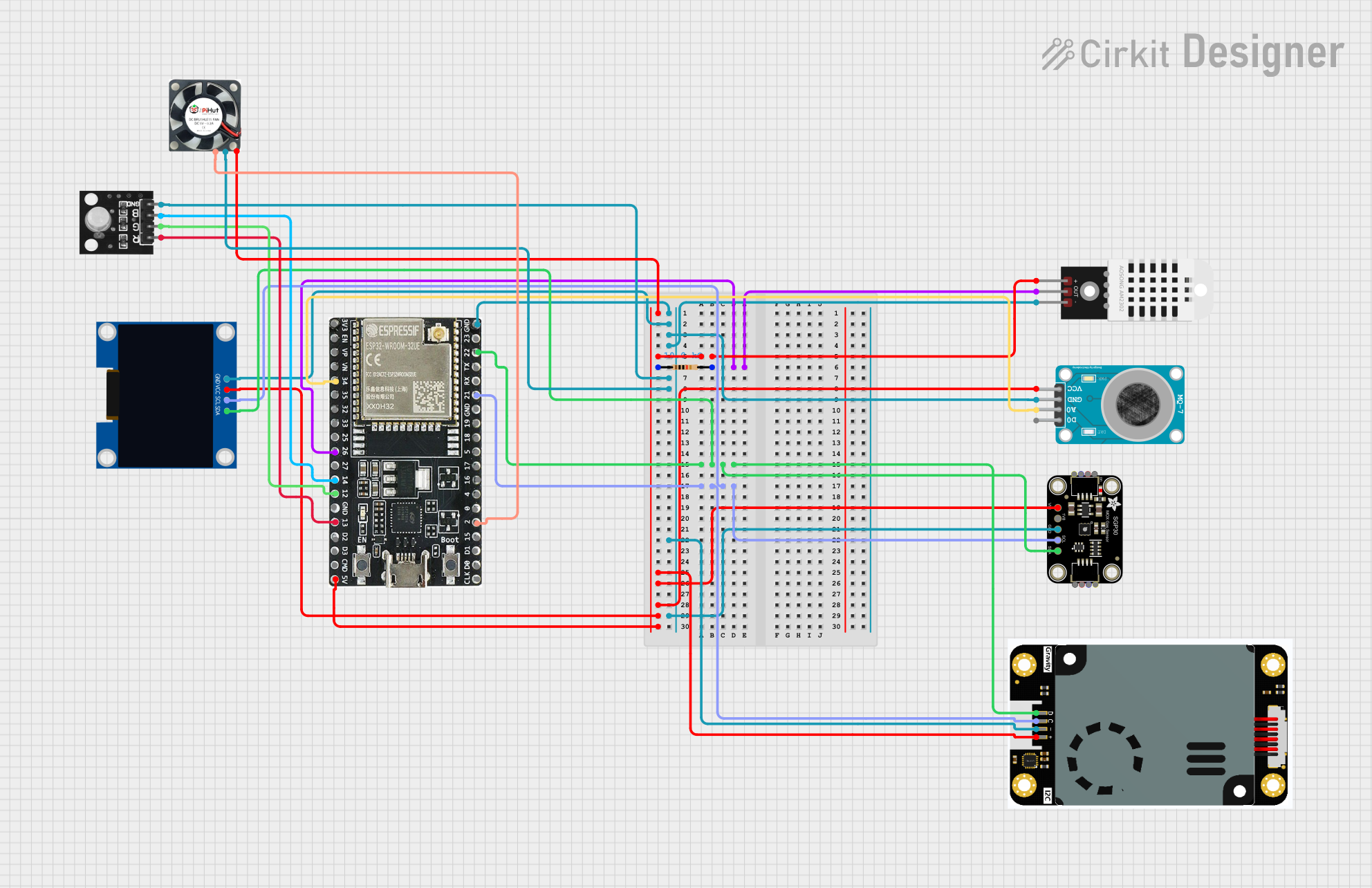
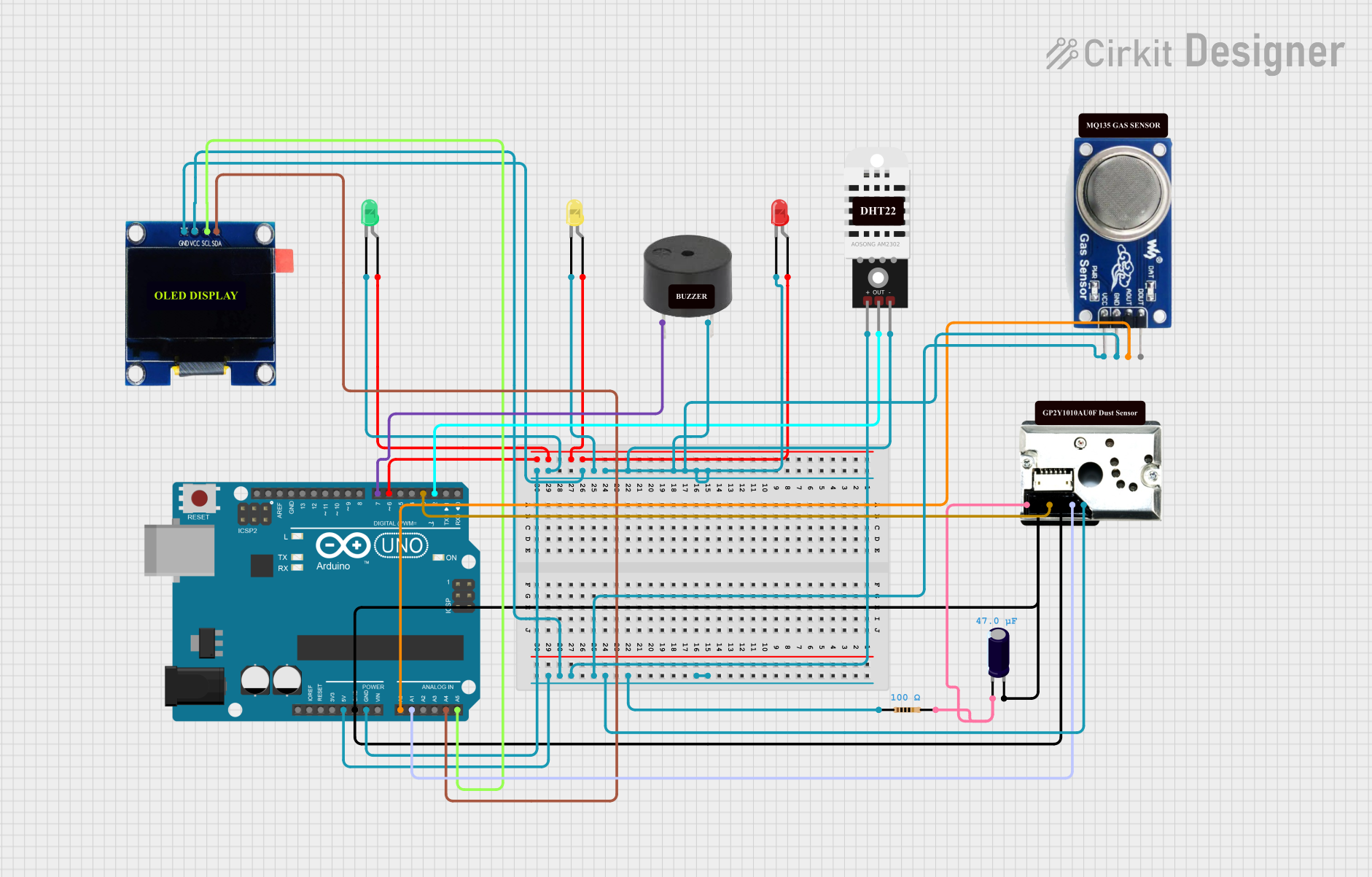
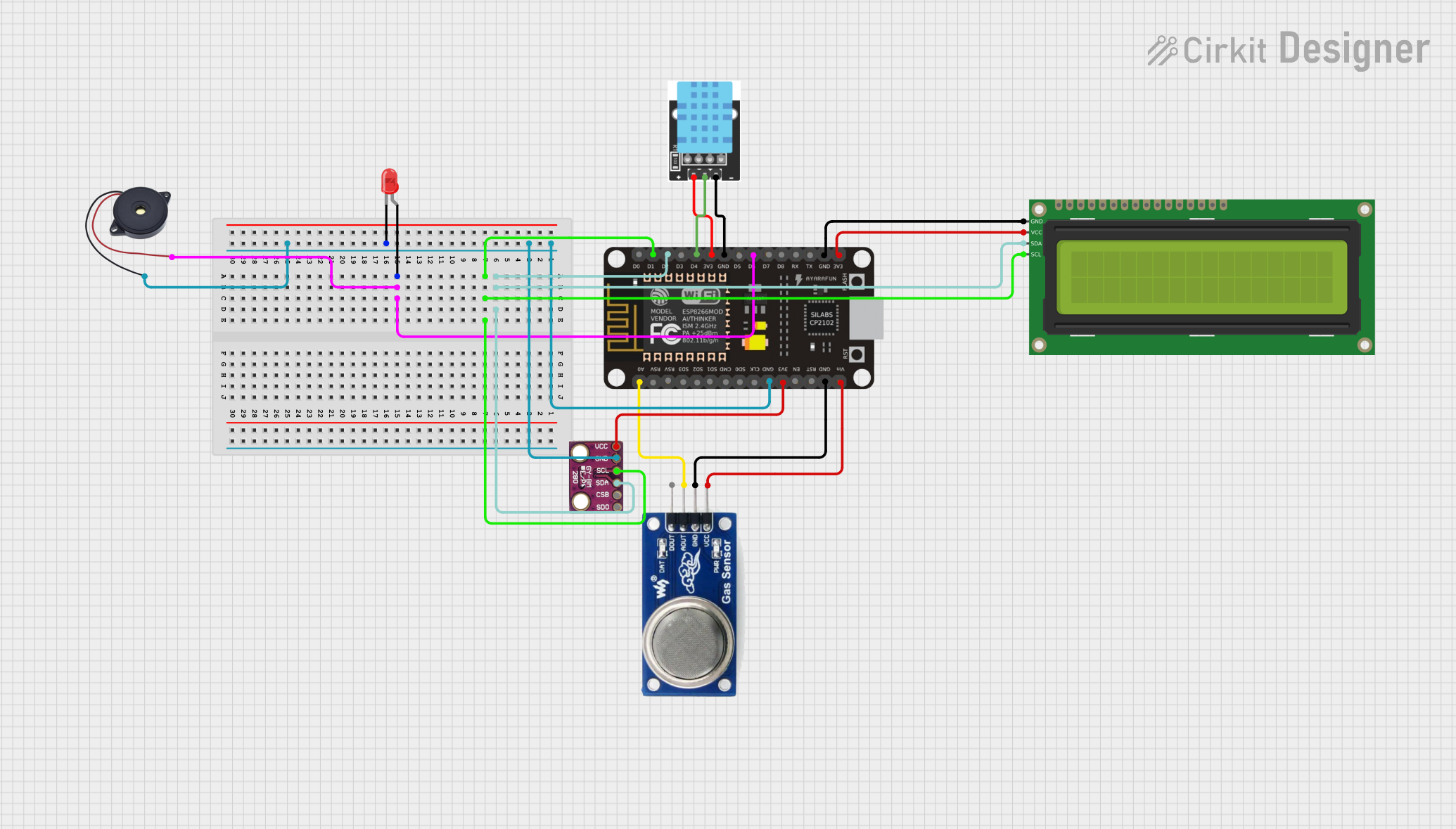
Explore Projects Built with Air quality sensor
Technical Specifications
Key Technical Details
- Measurement Range: Typically measures a range of pollutants such as CO2, VOCs, PM2.5, PM10, etc.
- Sensitivity: Varies based on the specific pollutant being measured.
- Accuracy: Depends on the sensor technology and calibration.
- Operating Voltage: Usually between 3.3V to 5V for most sensors.
- Output Signal: Analog or digital (I2C, UART, PWM).
- Operating Temperature Range: Often -10°C to +50°C for indoor sensors.
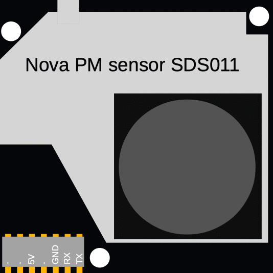
Pin Configuration and Descriptions
| Pin Number | Name | Description |
|---|---|---|
| 1 | VCC | Power supply (3.3V - 5V) |
| 2 | GND | Ground connection |
| 3 | OUT | Analog or digital output signal |
| 4 | RX | UART receive pin (if applicable) |
| 5 | TX | UART transmit pin (if applicable) |
| 6 | SCL | I2C clock line (if applicable) |
| 7 | SDA | I2C data line (if applicable) |
Usage Instructions
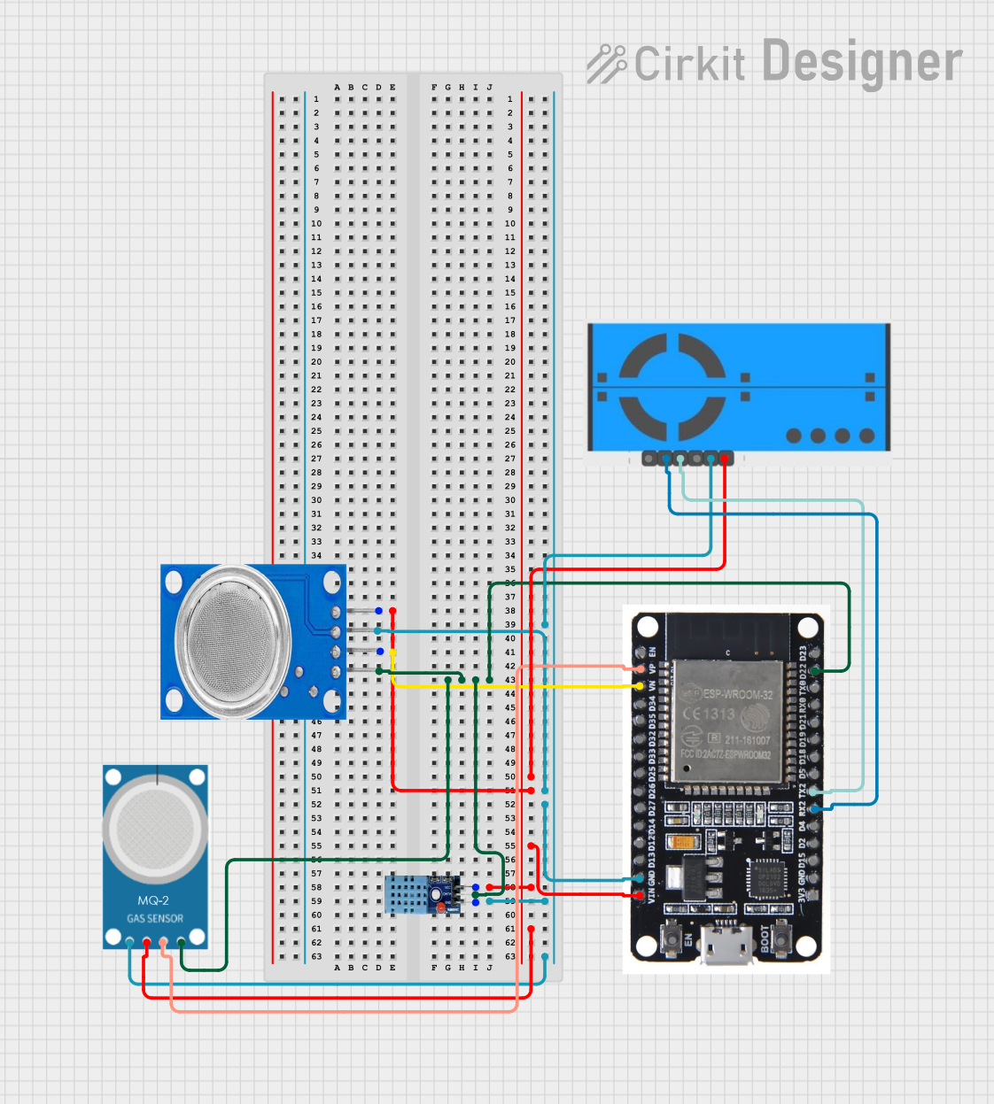
How to Use the Component in a Circuit
- Power Supply: Connect the VCC pin to a power source within the sensor's operating voltage range.
- Ground: Connect the GND pin to the ground of the power source.
- Signal Output: Connect the OUT pin to an analog or digital input on your microcontroller.
- Communication (if applicable): For digital sensors, connect RX and TX or SCL and SDA to the corresponding pins on your microcontroller for UART or I2C communication.
Important Considerations and Best Practices
- Calibration: Ensure the sensor is properly calibrated for accurate readings.
- Placement: Position the sensor where it can get a representative sample of the air, avoiding obstructions and direct airflow from vents or fans.
- Temperature and Humidity: Be aware of the sensor's operating temperature range and compensate for humidity if necessary.
- Interference: Keep the sensor away from sources of electromagnetic interference.
- Regular Maintenance: Clean the sensor periodically to prevent dust and other particles from affecting the readings.
Troubleshooting and FAQs
Common Issues
- Inaccurate Readings: This can be due to improper calibration, sensor placement, or a dirty sensor surface.
- No Output Signal: Check the power supply and connections to ensure the sensor is properly powered and connected.
Solutions and Tips
- Calibration: Follow the manufacturer's instructions for calibration.
- Cleaning: Use a soft brush or compressed air to gently clean the sensor.
- Connections: Verify all connections are secure and free from corrosion.
FAQs
Q: How often should the sensor be calibrated? A: Calibration frequency depends on the sensor's usage and the manufacturer's recommendations.
Q: Can the sensor be used outdoors? A: Some air quality sensors are designed for outdoor use, but check the specifications for environmental tolerances.
Q: What is the lifespan of an air quality sensor? A: The lifespan varies by sensor type and usage but typically ranges from 1 to 3 years.
Example Code for Arduino UNO
#include <Wire.h> // Include the I2C library (required for some sensors)

// Define sensor I2C address (if applicable)
#define SENSOR_I2C_ADDRESS 0xXX

void setup() {
  Serial.begin(9600); // Start serial communication at 9600 baud
  Wire.begin();       // Initialize I2C communication

  // Sensor initialization code (if required)
}

void loop() {
  // Read data from the sensor
  int airQuality = readAirQuality();

  // Output the air quality value
  Serial.println(airQuality);

  // Wait for a bit before reading again
  delay(1000);
}

int readAirQuality() {
  // Replace with actual sensor reading code
  // This is a placeholder to show where sensor reading logic would go
  int value = analogRead(A0); // Read the analog value from sensor
  return value;
}
Note: The example code provided is a generic template for an Arduino UNO. The actual implementation will vary depending on the specific air quality sensor model and communication protocol used. Always refer to the sensor's datasheet for precise programming details.