How to Use BMP280: Examples, Pinouts, and Specs
Introduction
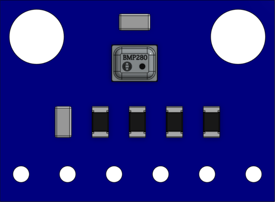
The BMP280 is a high-precision digital barometric pressure sensor designed to measure atmospheric pressure and temperature. It is a compact and energy-efficient component, making it ideal for a wide range of applications. The BMP280 is commonly used in weather stations, drones, and IoT devices for altitude measurement, environmental monitoring, and weather forecasting. Its I2C and SPI communication interfaces make it easy to integrate with microcontrollers and development boards like the Arduino UNO.
Explore Projects Built with BMP280
Explore Projects Built with BMP280
Technical Specifications
- Operating Voltage: 1.71V to 3.6V
- Current Consumption: 2.7 µA (typical in sleep mode), 650 µA (maximum in normal mode)
- Pressure Measurement Range: 300 hPa to 1100 hPa
- Temperature Measurement Range: -40°C to +85°C
- Pressure Resolution: 0.16 Pa
- Temperature Resolution: 0.01°C
- Communication Interfaces: I2C (up to 3.4 MHz) and SPI (up to 10 MHz)
- Package: 2.0 mm × 2.5 mm × 0.95 mm (LGA)
Pin Configuration and Descriptions
The BMP280 has 8 pins, as described in the table below:
| Pin | Name | Description |
|---|---|---|
| 1 | VDD | Power supply pin (1.71V to 3.6V). |
| 2 | GND | Ground pin. |
| 3 | SCL/SPC | Serial clock line for I2C or SPI communication. |
| 4 | SDA/SDI/SDO | Data line for I2C or SPI communication. |
| 5 | CSB | Chip select for SPI communication (active low). Tie to VDD for I2C mode. |
| 6 | SDO | SPI data output. Leave unconnected in I2C mode. |
| 7 | NC | Not connected. Leave floating. |
| 8 | VDDIO | I/O voltage supply pin. Typically connected to VDD. |
Usage Instructions
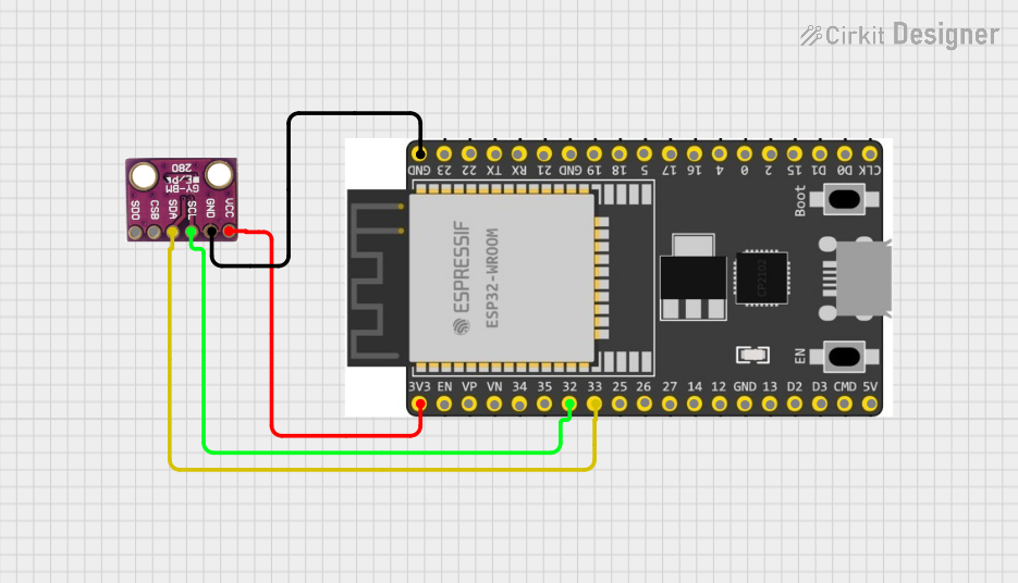
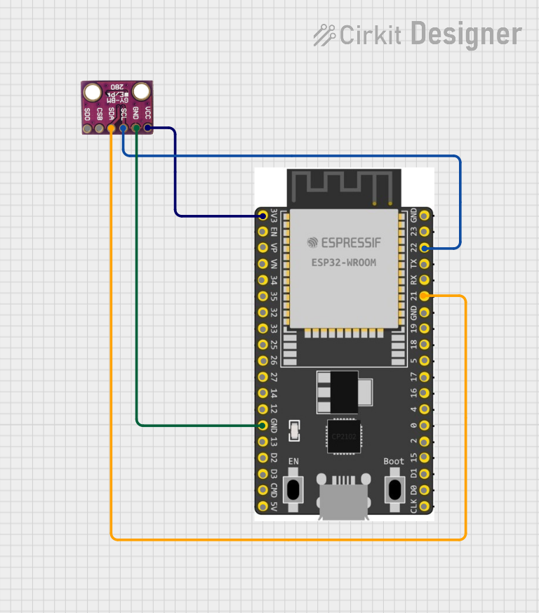
How to Use the BMP280 in a Circuit
- Power Supply: Connect the VDD pin to a 3.3V power source and the GND pin to ground.
- Communication Interface:
- For I2C mode:
- Connect the SCL pin to the I2C clock line of the microcontroller.
- Connect the SDA pin to the I2C data line of the microcontroller.
- Tie the CSB pin to VDD.
- For SPI mode:
- Connect the SCL pin to the SPI clock line.
- Connect the SDA pin to the SPI data input line.
- Connect the SDO pin to the SPI data output line.
- Connect the CSB pin to the SPI chip select line.
- For I2C mode:
- Pull-Up Resistors: Use 4.7kΩ pull-up resistors on the SCL and SDA lines for I2C communication.
- Bypass Capacitor: Place a 0.1 µF capacitor between VDD and GND for noise filtering.
Arduino UNO Example Code (I2C Mode)
Below is an example of how to interface the BMP280 with an Arduino UNO using the Adafruit BMP280 library:
#include <Wire.h>
#include <Adafruit_Sensor.h>
#include <Adafruit_BMP280.h>

// Create an instance of the BMP280 sensor
Adafruit_BMP280 bmp;

void setup() {
  Serial.begin(9600); // Initialize serial communication at 9600 baud
  if (!bmp.begin(0x76)) {
    // Initialize BMP280 with I2C address 0x76. If initialization fails, print error.
    Serial.println("Could not find a valid BMP280 sensor, check wiring!");
    while (1); // Halt execution if sensor is not found
  }

  // Configure the BMP280 sensor
  bmp.setSampling(Adafruit_BMP280::MODE_NORMAL,     // Normal mode
                  Adafruit_BMP280::SAMPLING_X2,     // Temperature oversampling x2
                  Adafruit_BMP280::SAMPLING_X16,    // Pressure oversampling x16
                  Adafruit_BMP280::FILTER_X16,      // Filter coefficient x16
                  Adafruit_BMP280::STANDBY_MS_500); // Standby time 500ms
}

void loop() {
  // Read and print temperature and pressure values
  Serial.print("Temperature = ");
  Serial.print(bmp.readTemperature());
  Serial.println(" *C");

  Serial.print("Pressure = ");
  Serial.print(bmp.readPressure());
  Serial.println(" Pa");

  Serial.print("Approx. Altitude = ");
  Serial.print(bmp.readAltitude(1013.25));
  // Calculate altitude assuming sea level pressure is 1013.25 hPa
  Serial.println(" m");

  delay(2000); // Wait for 2 seconds before the next reading
}
Important Considerations and Best Practices
- Ensure the BMP280 is powered within its specified voltage range (1.71V to 3.6V).
- Use appropriate pull-up resistors for I2C communication to ensure reliable data transfer.
- Avoid exposing the sensor to extreme temperatures or high humidity, as this may affect its accuracy.
- Calibrate the sensor if precise altitude measurements are required.
Troubleshooting and FAQs
Common Issues and Solutions
Sensor Not Detected:
- Ensure the I2C address (default: 0x76 or 0x77) matches the one in your code.
- Check the wiring and ensure proper connections between the sensor and microcontroller.
- Verify that pull-up resistors are used on the I2C lines.
Incorrect Readings:
- Ensure the sensor is not exposed to rapid temperature changes or vibrations.
- Verify that the sensor is configured correctly in the code (e.g., sampling rates, filter settings).
Communication Errors:
- Check the I2C or SPI clock speed and ensure it is within the sensor's supported range.
- Inspect the connections for loose wires or poor soldering.
FAQs
Q: Can the BMP280 measure altitude directly?
A: The BMP280 does not measure altitude directly but calculates it based on atmospheric pressure. You can use the readAltitude() function in the Adafruit library to estimate altitude, assuming a known sea-level pressure.
Q: What is the difference between the BMP280 and BME280?
A: The BMP280 measures pressure and temperature, while the BME280 includes an additional humidity sensor for environmental monitoring.
Q: Can the BMP280 operate at 5V?
A: No, the BMP280 operates at a maximum voltage of 3.6V. Use a level shifter if interfacing with a 5V microcontroller.
Q: How do I switch between I2C and SPI modes?
A: The communication mode is determined by the state of the CSB pin. Tie CSB to VDD for I2C mode or connect it to the SPI chip select line for SPI mode.