
How to Use Connector 2 In 6 Out: Examples, Pinouts, and Specs
 Design with Connector 2 In 6 Out in Cirkit Designer
Introduction
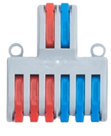
The Connector 2 In 6 Out by WAGO is a versatile signal distribution component designed to route two input signals to six output channels. This connector is widely used in audio systems, data communication networks, and industrial control systems where efficient signal splitting and distribution are required. Its compact design and reliable performance make it an essential component for applications requiring multiple signal outputs from a limited number of inputs.
Explore Projects Built with Connector 2 In 6 Out
 Open Project in Cirkit Designer
 Open Project in Cirkit Designer
 Open Project in Cirkit Designer
 Open Project in Cirkit Designer
Explore Projects Built with Connector 2 In 6 Out
Open Project in Cirkit DesignerOpen Project in Cirkit DesignerOpen Project in Cirkit DesignerOpen Project in Cirkit DesignerCommon Applications and Use Cases
- Audio Systems: Distributing stereo audio signals to multiple speakers or amplifiers.
- Data Communication: Splitting data signals for parallel processing or monitoring.
- Industrial Automation: Routing control signals to multiple actuators or sensors.
- Testing and Prototyping: Simplifying signal distribution during circuit testing.
Technical Specifications
The following table outlines the key technical details of the Connector 2 In 6 Out:
| Parameter | Specification |
|---|---|
| Manufacturer | WAGO |
| Input Channels | 2 |
| Output Channels | 6 |
| Voltage Rating | 0–250 V AC/DC |
| Current Rating | Up to 10 A per channel |
| Operating Temperature | -20°C to +70°C |
| Insulation Resistance | ≥ 10⁶ MΩ |
| Housing Material | Polyamide (PA66), flame-retardant |
| Mounting Type | DIN rail or panel mount |
| Wire Connection Type | Push-in CAGE CLAMP® technology |
Pin Configuration and Descriptions
The Connector 2 In 6 Out features a straightforward pin layout for easy wiring. Below is the pin configuration:
| Pin | Description |
|---|---|
| IN1 | Input signal 1 |
| IN2 | Input signal 2 |
| OUT1 | Output signal 1 (from IN1) |
| OUT2 | Output signal 2 (from IN1) |
| OUT3 | Output signal 3 (from IN1) |
| OUT4 | Output signal 4 (from IN2) |
| OUT5 | Output signal 5 (from IN2) |
| OUT6 | Output signal 6 (from IN2) |
Usage Instructions
How to Use the Connector in a Circuit
- Mounting: Secure the connector to a DIN rail or panel using the provided mounting slots.
- Wiring:
- Insert the input wires into the IN1 and IN2 terminals using the push-in CAGE CLAMP® mechanism.
- Connect the output wires to the desired OUT1–OUT6 terminals.
- Power On: Ensure the input signals are within the specified voltage and current ratings before powering the circuit.
- Testing: Verify that the signals are correctly distributed to the output channels using a multimeter or oscilloscope.
Important Considerations and Best Practices
- Signal Integrity: Use shielded cables for high-frequency or sensitive signals to minimize interference.
- Current Distribution: Ensure the total current drawn by all output channels does not exceed the input channel's rating.
- Temperature: Operate the connector within the specified temperature range to avoid damage.
- Maintenance: Periodically inspect the connector for loose wires or signs of wear.
Example: Using the Connector with an Arduino UNO
The Connector 2 In 6 Out can be used to distribute signals from an Arduino UNO to multiple devices. Below is an example of distributing a PWM signal:
/*
  Example: Distributing a PWM signal from Arduino UNO to multiple outputs
  using the WAGO Connector 2 In 6 Out.
*/

const int pwmPin = 9; // PWM output pin on Arduino UNO

void setup() {
  pinMode(pwmPin, OUTPUT); // Set the PWM pin as an output
}

void loop() {
  // Generate a PWM signal with a duty cycle of 50%
  analogWrite(pwmPin, 128); // 128 corresponds to 50% duty cycle (0-255 range)

  // The signal from pwmPin will be routed to multiple outputs via the connector.
  delay(1000); // Wait for 1 second
}
Note: Ensure the devices connected to the output channels are compatible with the PWM signal.
Troubleshooting and FAQs
Common Issues and Solutions
| Issue | Possible Cause | Solution |
|---|---|---|
| No signal at output channels | Loose or incorrect wiring | Verify all connections and reinsert wires |
| Signal distortion or noise | Interference or poor cable shielding | Use shielded cables and check grounding |
| Overheating of the connector | Exceeding current or voltage ratings | Reduce load or check input specifications |
| Uneven signal distribution | Faulty input signal or damaged connector | Test input signal and inspect the device |
FAQs
Can I use this connector for DC signals?
- Yes, the connector supports both AC and DC signals up to 250 V.
What is the maximum wire size supported?
- The push-in terminals support wires ranging from 0.2 mm² to 4 mm².
Can I use this connector for high-frequency signals?
- Yes, but ensure proper shielding and grounding to maintain signal integrity.
Is the connector suitable for outdoor use?
- The connector is not weatherproof. Use it in indoor or protected environments.
By following this documentation, users can effectively integrate the Connector 2 In 6 Out into their projects for reliable and efficient signal distribution.