How to Use SABERTOOTH 2X32 MOTOR CONTROLLER: Examples, Pinouts, and Specs
Introduction
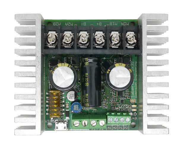
The Sabertooth 2x32 Motor Controller is a versatile dual-channel motor controller designed for controlling DC motors. It is capable of handling up to 32A per channel continuously, making it ideal for high-power applications. This controller supports multiple control modes, including PWM, analog voltage, serial, and packetized serial, providing flexibility for a wide range of robotics and automation projects. Additionally, it features built-in thermal protection, overcurrent protection, and regenerative braking.
Explore Projects Built with SABERTOOTH 2X32 MOTOR CONTROLLER
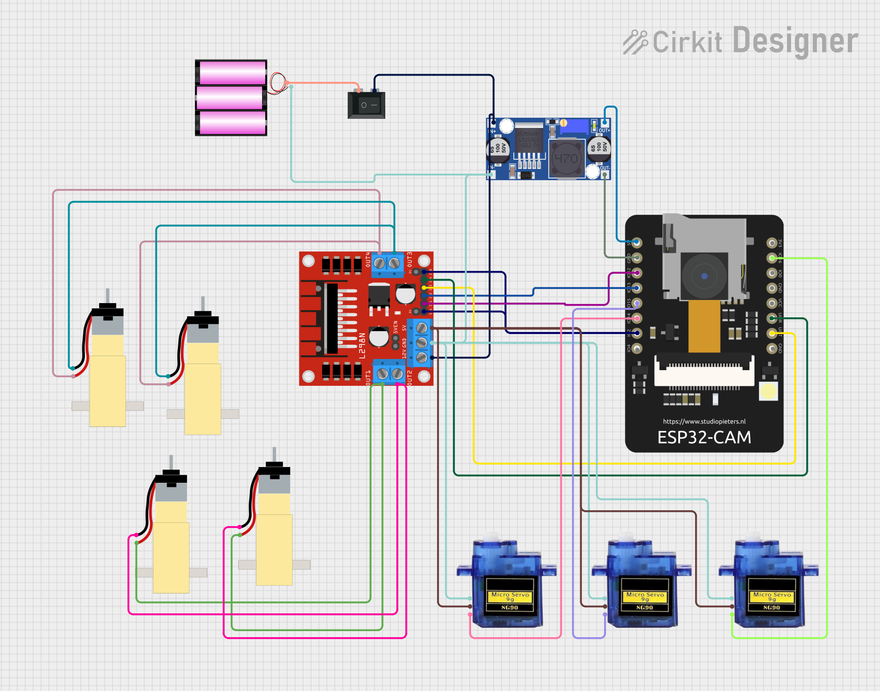
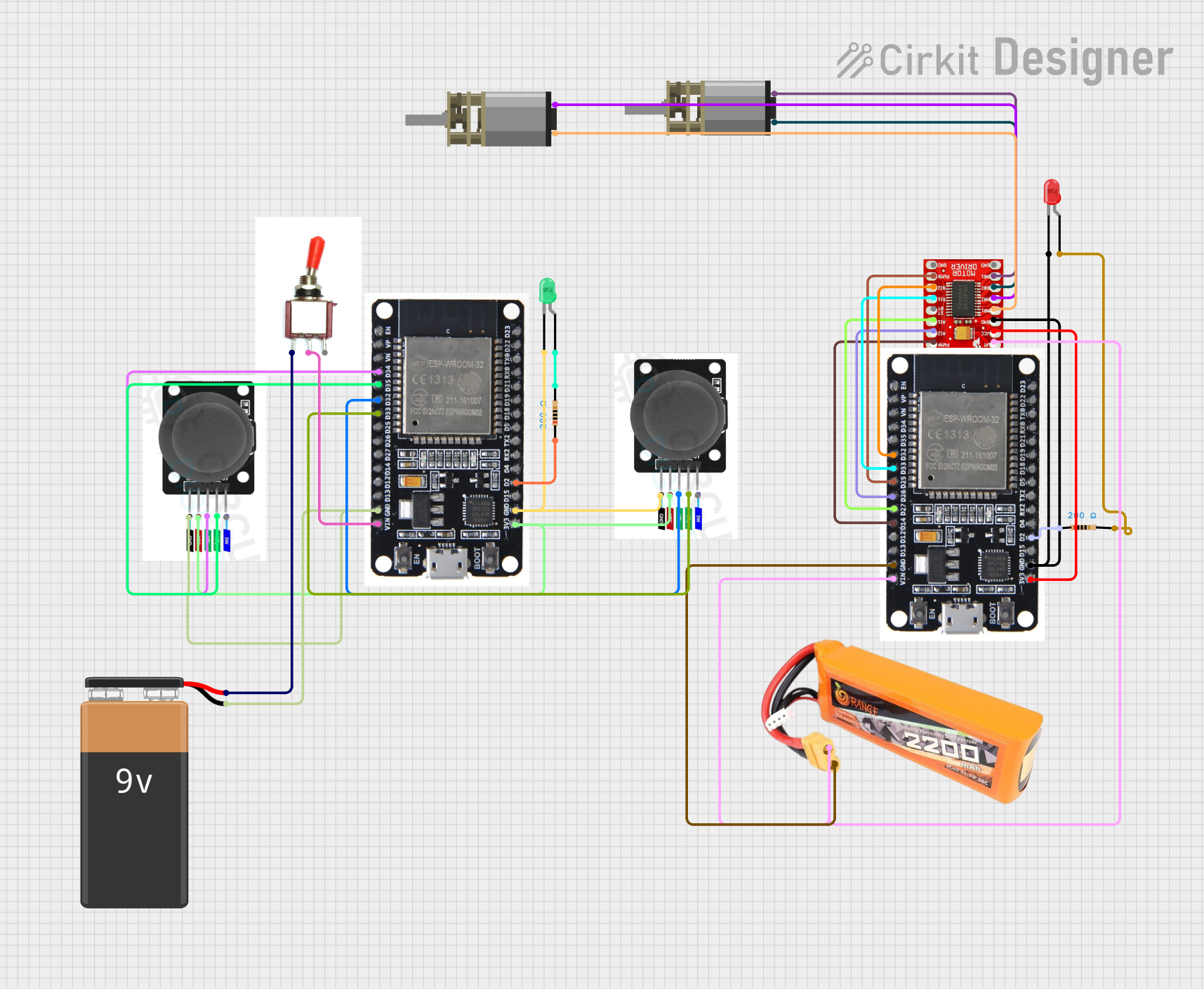
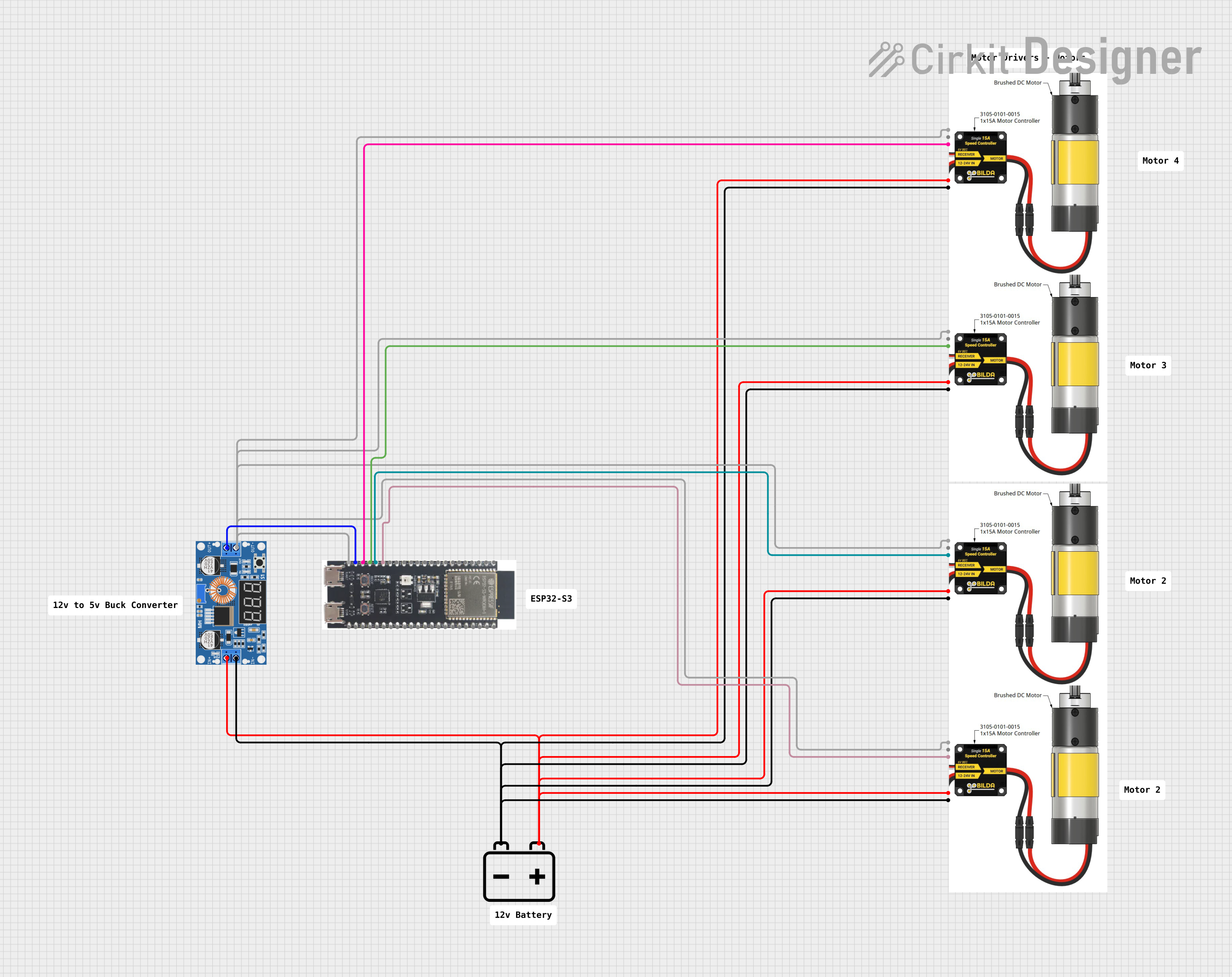
Explore Projects Built with SABERTOOTH 2X32 MOTOR CONTROLLER
Common Applications and Use Cases
- Robotics (e.g., mobile robots, robotic arms)
- Automated guided vehicles (AGVs)
- Electric wheelchairs
- Conveyor systems
- Remote-controlled vehicles
- Industrial automation
Technical Specifications
Key Technical Details
| Parameter | Value |
|---|---|
| Channels | 2 |
| Continuous Current (per channel) | 32A |
| Peak Current (per channel) | 64A (for a few seconds) |
| Input Voltage Range | 6V to 30V |
| Control Modes | PWM, Analog Voltage, Serial, Packetized Serial |
| Regenerative Braking | Yes |
| Thermal Protection | Yes |
| Overcurrent Protection | Yes |
| Dimensions | 3.25" x 2.75" x 1" (82.5mm x 70mm x 25mm) |
| Weight | 120g |
Pin Configuration and Descriptions
| Pin Name | Description |
|---|---|
| S1 | Signal input for channel 1 (PWM, analog, or serial input) |
| S2 | Signal input for channel 2 (PWM, analog, or serial input) |
| 0V | Ground connection for signal inputs |
| B+ | Positive terminal for battery/power supply |
| B- | Negative terminal for battery/power supply |
| M1A | Motor 1 output terminal A |
| M1B | Motor 1 output terminal B |
| M2A | Motor 2 output terminal A |
| M2B | Motor 2 output terminal B |
| USB | USB port for configuration and firmware updates |
Usage Instructions
How to Use the Component in a Circuit
- Power Connection: Connect the B+ and B- terminals to a suitable power source (6V to 30V). Ensure the power supply can handle the current requirements of your motors.
- Motor Connection: Connect the DC motors to the M1A/M1B and M2A/M2B terminals. Ensure proper polarity for desired motor direction.
- Signal Input: Choose a control mode (PWM, analog, or serial) and connect the corresponding signal to the S1 and S2 pins. For example:
- For PWM control, connect the PWM signal from a microcontroller (e.g., Arduino) to S1 and S2.
- For analog control, connect a potentiometer or analog voltage source.
- Ground Connection: Connect the 0V pin to the ground of your control circuit.
- Configuration: Use the USB port to configure the controller using the Dimension Engineering DEScribe software if needed.
Important Considerations and Best Practices
- Heat Dissipation: Ensure adequate ventilation or use a heatsink if operating near the maximum current rating.
- Power Supply: Use a power supply with sufficient current capacity to avoid voltage drops or damage.
- Signal Grounding: Always connect the ground of the signal source to the 0V pin of the controller.
- Regenerative Braking: Be aware that regenerative braking can feed current back into the power supply. Use a battery or a power supply capable of handling this.
Example: Using with Arduino UNO (PWM Control)
Below is an example of controlling two DC motors using the Sabertooth 2x32 in PWM mode with an Arduino UNO.
// Example code for controlling Sabertooth 2x32 Motor Controller with Arduino UNO
// This code uses PWM signals to control motor speed and direction.

#define MOTOR1_PWM 9  // PWM pin for Motor 1
#define MOTOR2_PWM 10 // PWM pin for Motor 2

void setup() {
  pinMode(MOTOR1_PWM, OUTPUT); // Set Motor 1 PWM pin as output
  pinMode(MOTOR2_PWM, OUTPUT); // Set Motor 2 PWM pin as output
}

void loop() {
  // Example: Set Motor 1 to 50% speed forward
  analogWrite(MOTOR1_PWM, 128); // 128/255 = 50% duty cycle

  // Example: Set Motor 2 to 75% speed forward
  analogWrite(MOTOR2_PWM, 192); // 192/255 = 75% duty cycle

  delay(2000); // Run motors for 2 seconds

  // Stop both motors
  analogWrite(MOTOR1_PWM, 0); // 0% duty cycle (stop)
  analogWrite(MOTOR2_PWM, 0); // 0% duty cycle (stop)

  delay(2000); // Wait for 2 seconds before repeating
}
Troubleshooting and FAQs
Common Issues and Solutions
Motors Not Running
- Cause: Incorrect wiring or insufficient power supply.
- Solution: Double-check all connections and ensure the power supply meets the voltage and current requirements.
Overheating
- Cause: Operating near or above the maximum current rating without proper cooling.
- Solution: Improve ventilation or add a heatsink to the controller.
Erratic Motor Behavior
- Cause: Noise or interference in the signal lines.
- Solution: Use shielded cables for signal connections and ensure proper grounding.
Regenerative Braking Issues
- Cause: Power supply unable to handle regenerative current.
- Solution: Use a battery or a power supply with regenerative braking support.
FAQs
Can I use the Sabertooth 2x32 with a 24V power supply? Yes, the controller supports input voltages up to 30V, so a 24V power supply is suitable.
What happens if I exceed the current rating? The controller has built-in overcurrent protection and will shut down temporarily to prevent damage.
Can I control the Sabertooth 2x32 using a Raspberry Pi? Yes, you can use the Raspberry Pi's GPIO pins to send PWM or serial signals to the controller.
Is the Sabertooth 2x32 compatible with brushless motors? No, the Sabertooth 2x32 is designed for brushed DC motors only.