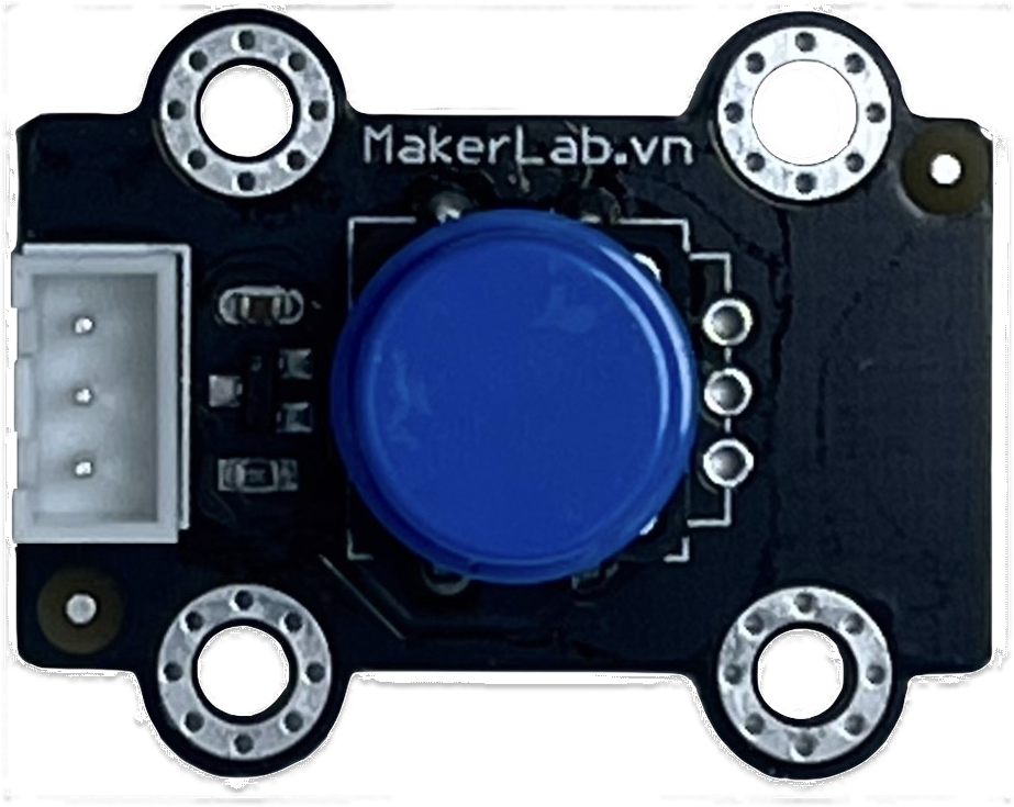
How to Use MKE-M02 Push Button Tact Switch Module: Examples, Pinouts, and Specs
Introduction
The MKE-M02 Push Button Tact Switch Module is a compact and versatile electronic component used for adding a tactile interface to your projects. It is commonly used to input digital signals into a microcontroller or other digital circuits by pressing the button, which either makes or breaks the circuit. This module is widely used in applications such as:
- User input for microcontroller projects
- Interactive installations
- Prototyping and educational kits
- DIY electronics and hobby projects
Explore Projects Built with MKE-M02 Push Button Tact Switch Module

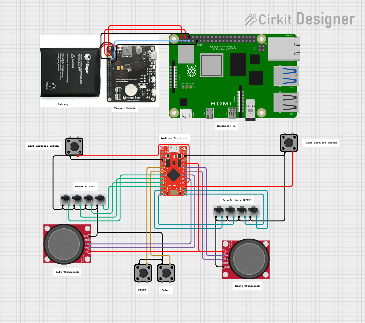


Explore Projects Built with MKE-M02 Push Button Tact Switch Module
Technical Specifications
Key Technical Details
- Voltage: 3.3V to 5V
- Current: 10mA (typical when active)
- Contact Resistance: ≤ 50mΩ
- Insulation Resistance: ≥ 100MΩ at 500V DC
- Dielectric Strength: 250V AC for 1 min
- Operating Force: 180/230 (±20gf)
- Life Expectancy: 100,000 cycles
Pin Configuration and Descriptions
| Pin Number | Description |
|---|---|
| 1 | Signal (SIG) |
| 2 | Ground (GND) |
| 3 | Power Supply (VCC) |
Usage Instructions
How to Use the Component in a Circuit
- Power Connection: Connect the VCC pin to the power supply (3.3V or 5V, depending on your circuit requirements).
- Ground Connection: Connect the GND pin to the ground of your power supply.
- Signal Connection: Connect the SIG pin to a digital input pin on your microcontroller.
Important Considerations and Best Practices
- Use a pull-up or pull-down resistor to ensure a stable signal when the button is not pressed.
- Debounce the button either through hardware (with a capacitor) or software to prevent false triggering from mechanical vibrations.
- Avoid applying excessive force to the button to prevent damage.
Example Code for Arduino UNO
// Define the pin connected to the push button module
const int buttonPin = 2;
// Variable for storing the button state
int buttonState = 0;

void setup() {
  // Initialize the button pin as an input
  pinMode(buttonPin, INPUT);
  // Begin serial communication at 9600 baud rate
  Serial.begin(9600);
}

void loop() {
  // Read the state of the button
  buttonState = digitalRead(buttonPin);

  // Check if the button is pressed
  if (buttonState == HIGH) {
    // If the button is pressed, print this message
    Serial.println("Button Pressed");
  } else {
    // If the button is not pressed, print this message
    Serial.println("Button Released");
  }
  // Delay a little bit to avoid bouncing
  delay(50);
}
Troubleshooting and FAQs
Common Issues
- Button does not respond: Ensure that all connections are secure and the button is properly wired to the microcontroller.
- False triggering: Implement debouncing in your code or add a hardware debouncer to the circuit.
- Inconsistent readings: Check for any damage to the button or loose connections.
Solutions and Tips for Troubleshooting
- Double-check wiring against the pin configuration table.
- Use a multimeter to ensure the button is functioning correctly when pressed.
- Review your code for proper button state handling and debouncing logic.
FAQs
Q: Can I use this module with a 3.3V system? A: Yes, the MKE-M02 is compatible with both 3.3V and 5V systems.
Q: Do I need an external resistor for the module? A: It is recommended to use an external pull-up or pull-down resistor to ensure a stable signal.
Q: How can I prevent the button from bouncing? A: You can prevent bouncing by using a debounce algorithm in your code or by adding a small capacitor (e.g., 10nF) between the SIG pin and ground.
Q: Is the module suitable for rapid button presses? A: Yes, the module can handle rapid actuation, but ensure that your debouncing method can keep up with the press rate.
This documentation provides a comprehensive guide to using the MKE-M02 Push Button Tact Switch Module in your projects. For further assistance, consult the manufacturer's datasheet or contact technical support.