Cirkit Designer Logo
Cirkit Designer
Your all-in-one circuit design IDE
Home / 
Component Documentation

How to Use GMOD-WS2812B: Examples, Pinouts, and Specs

Image of GMOD-WS2812B
Cirkit Designer LogoDesign with GMOD-WS2812B in Cirkit Designer

Introduction

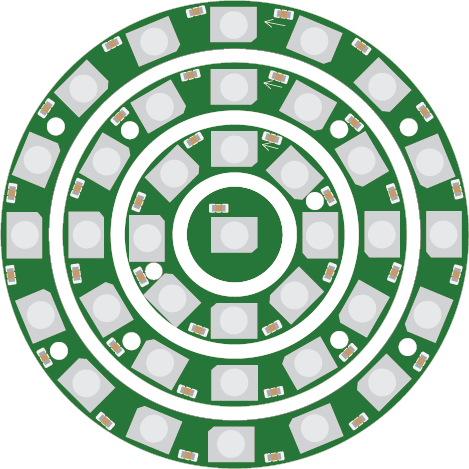
The GMOD-WS2812B is a smart RGB LED module manufactured by PCBCUPID (Part ID: GM006). This module integrates an RGB LED with a built-in driver, enabling individual control of each LED's color and brightness. It operates via a single data line, simplifying wiring and control. The GMOD-WS2812B is widely used in applications such as:

  • Decorative lighting (e.g., holiday lights, ambient lighting)
  • LED displays and signage
  • DIY electronics projects
  • Wearable technology
  • Interactive art installations

Its compact design and ease of use make it a popular choice for both hobbyists and professionals.

Explore Projects Built with GMOD-WS2812B

Use Cirkit Designer to design, explore, and prototype these projects online. Some projects support real-time simulation. Click "Open Project" to start designing instantly!
Arduino Mega 2560 and Raspberry Pi 4B Controlled WS2812 RGB LED Strip
Image of circuit_image: A project utilizing GMOD-WS2812B in a practical application
This circuit features an Arduino Mega 2560 microcontroller programmed to control a WS2812 RGB LED strip and a white LED, indicating status or providing user feedback. The Arduino and the LED strip are powered by a common 5V supply, and the circuit includes interfacing with a Raspberry Pi 4B for potential communication or coordination between the two boards.
Cirkit Designer LogoOpen Project in Cirkit Designer
Wi-Fi Controlled LED Strip with Wemos D1 Mini and IKEA Trådfri Driver
Image of WLED Diskbänken: A project utilizing GMOD-WS2812B in a practical application
This circuit is designed to control a WS2812 RGB LED strip using a Wemos D1 Mini microcontroller running WLED software. The circuit includes an IKEA Trådfri LED driver that converts 24V to 5V via an LM2596 voltage regulator, and an nMOS transistor to switch the LED strip's ground connection. The setup is intended for lighting applications, such as under-cabinet lighting in a kitchen.
Cirkit Designer LogoOpen Project in Cirkit Designer
Arduino UNO Controlled RGB LED Matrix with Bluetooth Connectivity and Audio Output
Image of the bell : A project utilizing GMOD-WS2812B in a practical application
This is an interactive display and communication circuit. It uses an Arduino UNO to drive multiple WS2812 RGB LED matrices for visual output, interfaces with a DS3231 RTC for time-related functions, and communicates wirelessly via an HC-05 Bluetooth module. Additionally, it features audio output capabilities through a speaker connected to a PAM8403 audio amplifier.
Cirkit Designer LogoOpen Project in Cirkit Designer
Wi-Fi Controlled RGB LED Strip with ESP32
Image of test: A project utilizing GMOD-WS2812B in a practical application
This circuit consists of an ESP32 microcontroller connected to a WS2812 RGB LED strip. The ESP32 controls the LED strip via its D2 pin, providing data input, while the 5V and GND pins of the LED strip are powered by the ESP32's Vin and GND pins, respectively.
Cirkit Designer LogoOpen Project in Cirkit Designer

Explore Projects Built with GMOD-WS2812B

Use Cirkit Designer to design, explore, and prototype these projects online. Some projects support real-time simulation. Click "Open Project" to start designing instantly!
Image of circuit_image: A project utilizing GMOD-WS2812B in a practical application
Arduino Mega 2560 and Raspberry Pi 4B Controlled WS2812 RGB LED Strip
This circuit features an Arduino Mega 2560 microcontroller programmed to control a WS2812 RGB LED strip and a white LED, indicating status or providing user feedback. The Arduino and the LED strip are powered by a common 5V supply, and the circuit includes interfacing with a Raspberry Pi 4B for potential communication or coordination between the two boards.
Cirkit Designer LogoOpen Project in Cirkit Designer
Image of WLED Diskbänken: A project utilizing GMOD-WS2812B in a practical application
Wi-Fi Controlled LED Strip with Wemos D1 Mini and IKEA Trådfri Driver
This circuit is designed to control a WS2812 RGB LED strip using a Wemos D1 Mini microcontroller running WLED software. The circuit includes an IKEA Trådfri LED driver that converts 24V to 5V via an LM2596 voltage regulator, and an nMOS transistor to switch the LED strip's ground connection. The setup is intended for lighting applications, such as under-cabinet lighting in a kitchen.
Cirkit Designer LogoOpen Project in Cirkit Designer
Image of the bell : A project utilizing GMOD-WS2812B in a practical application
Arduino UNO Controlled RGB LED Matrix with Bluetooth Connectivity and Audio Output
This is an interactive display and communication circuit. It uses an Arduino UNO to drive multiple WS2812 RGB LED matrices for visual output, interfaces with a DS3231 RTC for time-related functions, and communicates wirelessly via an HC-05 Bluetooth module. Additionally, it features audio output capabilities through a speaker connected to a PAM8403 audio amplifier.
Cirkit Designer LogoOpen Project in Cirkit Designer
Image of test: A project utilizing GMOD-WS2812B in a practical application
Wi-Fi Controlled RGB LED Strip with ESP32
This circuit consists of an ESP32 microcontroller connected to a WS2812 RGB LED strip. The ESP32 controls the LED strip via its D2 pin, providing data input, while the 5V and GND pins of the LED strip are powered by the ESP32's Vin and GND pins, respectively.
Cirkit Designer LogoOpen Project in Cirkit Designer

Technical Specifications

Below are the key technical details of the GMOD-WS2812B:

Parameter Value
Operating Voltage 3.3V to 5.5V
Operating Current ~20mA per LED (at full brightness)
Communication Protocol Single-wire (WS2812B protocol)
LED Color Depth 24-bit (8 bits per channel: R, G, B)
Maximum Refresh Rate 400 Hz
Operating Temperature -25°C to +80°C
Dimensions 5mm x 5mm (per LED module)

Pin Configuration

The GMOD-WS2812B module has three pins, as described in the table below:

Pin Name Pin Number Description
VDD 1 Power supply input (3.3V to 5.5V)
GND 2 Ground connection
DIN 3 Data input for controlling the LED module

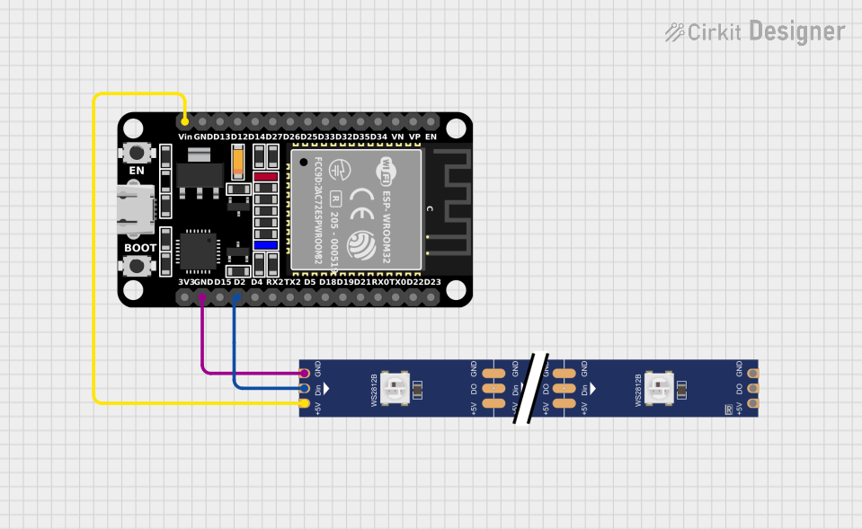
Note: The module also supports chaining multiple LEDs by connecting the DOUT pin of one module to the DIN pin of the next.

Usage Instructions

How to Use the GMOD-WS2812B in a Circuit

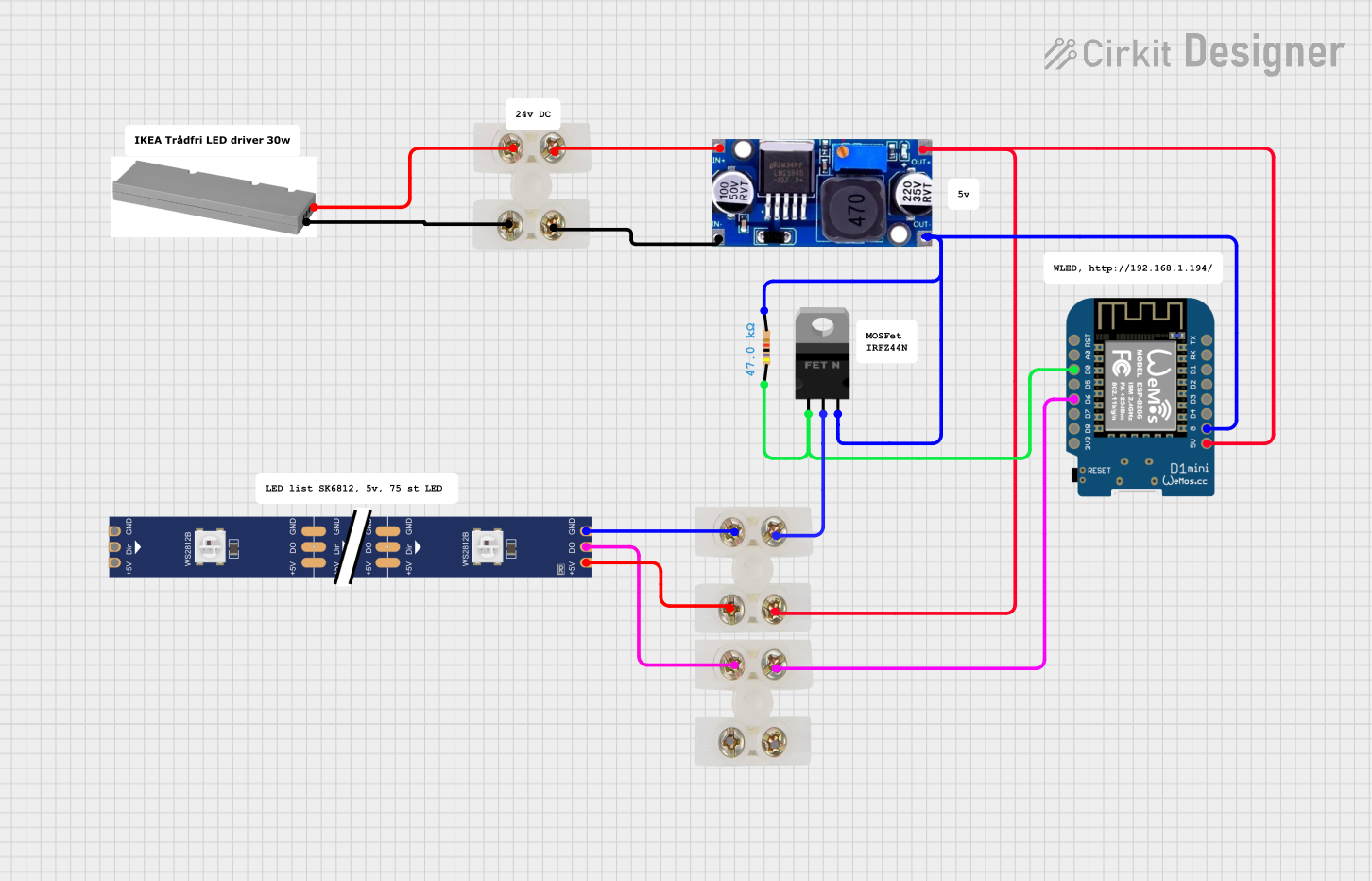
  1. Power Supply: Connect the VDD pin to a 5V power source and the GND pin to ground. Ensure the power supply can handle the total current draw of all LEDs in the chain.
  2. Data Line: Connect the DIN pin to a microcontroller's digital output pin. Use a resistor (330-500Ω) in series with the data line to reduce noise.
  3. Capacitor: Place a 1000µF capacitor across the VDD and GND pins to stabilize the power supply.
  4. Chaining LEDs: To chain multiple modules, connect the DOUT pin of one module to the DIN pin of the next.

Arduino UNO Example Code

Below is an example of how to control the GMOD-WS2812B using an Arduino UNO and the Adafruit NeoPixel library:

#include <Adafruit_NeoPixel.h>

// Define the number of LEDs in the chain
#define NUM_LEDS 8

// Define the pin connected to the DIN pin of the GMOD-WS2812B
#define DATA_PIN 6

// Create a NeoPixel object
Adafruit_NeoPixel strip = Adafruit_NeoPixel(NUM_LEDS, DATA_PIN, NEO_GRB + NEO_KHZ800);

void setup() {
  strip.begin();  // Initialize the LED strip
  strip.show();   // Turn off all LEDs initially
}

void loop() {
  // Example: Cycle through colors
  for (int i = 0; i < strip.numPixels(); i++) {
    strip.setPixelColor(i, strip.Color(255, 0, 0)); // Set LED to red
    strip.show();                                   // Update the strip
    delay(100);                                     // Wait 100ms
  }

  delay(500); // Pause before the next cycle
}

Important Notes:

  • Install the Adafruit NeoPixel library via the Arduino Library Manager before uploading the code.
  • Ensure the Arduino's 5V pin can supply sufficient current for the LEDs. For larger setups, use an external power supply.

Best Practices

  • Use a level shifter if the microcontroller operates at 3.3V logic levels to ensure reliable communication with the GMOD-WS2812B.
  • Avoid powering too many LEDs directly from the microcontroller. Use an external power source for larger setups.
  • Keep the data line as short as possible to minimize signal degradation.

Troubleshooting and FAQs

Common Issues and Solutions

  1. LEDs Not Lighting Up

    • Cause: Incorrect wiring or insufficient power supply.
    • Solution: Double-check all connections and ensure the power supply meets the current requirements.
  2. Flickering or Unstable Colors

    • Cause: Noise on the data line or insufficient power decoupling.
    • Solution: Add a 330-500Ω resistor in series with the data line and a 1000µF capacitor across the power supply.
  3. Only the First LED Works

    • Cause: Data signal not propagating to subsequent LEDs.
    • Solution: Verify the connection between the DOUT pin of one module and the DIN pin of the next.
  4. Colors Are Incorrect

    • Cause: Incorrect color order in the code.
    • Solution: Ensure the color order in the code matches the module's configuration (e.g., NEO_GRB).

FAQs

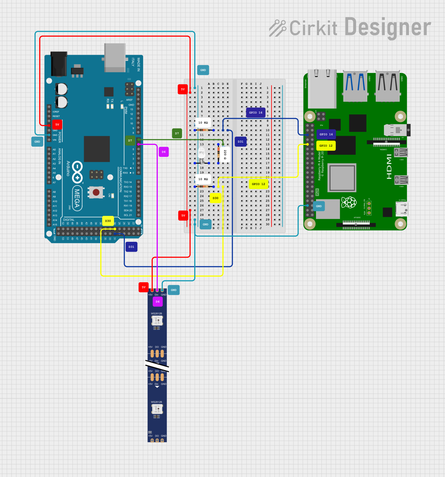
  • Can I control the GMOD-WS2812B with a Raspberry Pi? Yes, the GMOD-WS2812B can be controlled using a Raspberry Pi. Use libraries like rpi_ws281x for Python.

  • What is the maximum number of LEDs I can chain? Theoretically, you can chain hundreds of LEDs, but the practical limit depends on the power supply and microcontroller's memory.

  • Do I need a heatsink for the GMOD-WS2812B? No, the module is designed to operate without a heatsink under normal conditions. However, ensure proper ventilation for large arrays.

By following this documentation, you can effectively integrate the GMOD-WS2812B into your projects and create stunning lighting effects!