How to Use DPDT Relay Base Layout: Examples, Pinouts, and Specs
Introduction
A Double Pole Double Throw (DPDT) relay base layout is a configuration used to connect a DPDT relay to a circuit. This layout facilitates the control of two independent circuits using a single relay, making it highly versatile for switching applications. DPDT relays are commonly used in automation, motor control, and signal routing, where precise control of multiple circuits is required.
Explore Projects Built with DPDT Relay Base Layout


Explore Projects Built with DPDT Relay Base Layout
Common Applications and Use Cases
- Motor Direction Control: Reversing the polarity of DC motors.
- Signal Switching: Routing signals between different devices or circuits.
- Power Switching: Controlling two separate power circuits simultaneously.
- Home Automation: Switching between different power sources or devices.
- Industrial Automation: Controlling machinery or equipment with multiple states.
Technical Specifications
Key Technical Details
- Relay Type: Double Pole Double Throw (DPDT)
- Voltage Rating: Typically 5V, 12V, or 24V (depending on the relay used)
- Current Rating: Varies, commonly 5A to 10A per pole
- Contact Configuration: 2 poles, each with Normally Open (NO) and Normally Closed (NC) contacts
- Base Material: Plastic or phenolic with metal terminals
- Mounting: Screw terminals or PCB mount
Pin Configuration and Descriptions
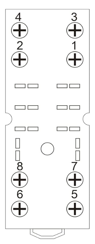
The DPDT relay base layout typically consists of 8 pins. Below is the pin configuration:
| Pin Number | Description | Functionality |
|---|---|---|
| 1 | Coil Terminal 1 | Connects to one side of the relay coil |
| 2 | Coil Terminal 2 | Connects to the other side of the relay coil |
| 3 | Common Terminal for Pole 1 (COM1) | Input for the first circuit |
| 4 | Normally Closed for Pole 1 (NC1) | Closed connection when the relay is OFF |
| 5 | Normally Open for Pole 1 (NO1) | Open connection when the relay is OFF |
| 6 | Common Terminal for Pole 2 (COM2) | Input for the second circuit |
| 7 | Normally Closed for Pole 2 (NC2) | Closed connection when the relay is OFF |
| 8 | Normally Open for Pole 2 (NO2) | Open connection when the relay is OFF |
Usage Instructions
How to Use the Component in a Circuit
- Identify the Pins: Refer to the pin configuration table to identify the coil, common, NO, and NC pins.
- Connect the Coil: Attach the relay coil terminals (pins 1 and 2) to the control circuit. Ensure the voltage matches the relay's rated coil voltage.
- Connect the Load:
- For the first circuit, connect the input to COM1 (pin 3), the normally closed load to NC1 (pin 4), and the normally open load to NO1 (pin 5).
- For the second circuit, connect the input to COM2 (pin 6), the normally closed load to NC2 (pin 7), and the normally open load to NO2 (pin 8).
- Control the Relay: Apply the appropriate voltage to the coil terminals to switch the relay. When the relay is energized, the common terminals (COM1 and COM2) will connect to the normally open terminals (NO1 and NO2). When de-energized, they will connect to the normally closed terminals (NC1 and NC2).
Important Considerations and Best Practices
- Voltage Matching: Ensure the control voltage matches the relay's coil voltage rating.
- Current Rating: Do not exceed the relay's current rating for each pole.
- Flyback Diode: Use a flyback diode across the coil terminals to protect the control circuit from voltage spikes when the relay is de-energized.
- Isolation: Ensure proper electrical isolation between the control and load circuits.
- Mounting: Secure the relay base firmly to prevent loose connections.
Example: Connecting a DPDT Relay to an Arduino UNO
Below is an example of how to control a DPDT relay using an Arduino UNO:
// Define the pin connected to the relay module
const int relayPin = 7;

void setup() {
  // Set the relay pin as an output
  pinMode(relayPin, OUTPUT);
}

void loop() {
  // Turn the relay ON
  digitalWrite(relayPin, HIGH);
  delay(1000); // Keep the relay ON for 1 second

  // Turn the relay OFF
  digitalWrite(relayPin, LOW);
  delay(1000); // Keep the relay OFF for 1 second
}
Notes:
- Connect the relay module's control input to pin 7 of the Arduino.
- Use an external power source if the relay requires more current than the Arduino can supply.
Troubleshooting and FAQs
Common Issues and Solutions
Relay Not Switching:
- Cause: Insufficient voltage or current to the coil.
- Solution: Verify the control voltage and current match the relay's specifications.
Chattering or Unstable Operation:
- Cause: Noise or insufficient power supply.
- Solution: Add a capacitor across the power supply or use a flyback diode.
Load Not Switching:
- Cause: Incorrect wiring of the load to the relay terminals.
- Solution: Double-check the connections to the COM, NO, and NC terminals.
Overheating:
- Cause: Exceeding the relay's current rating.
- Solution: Use a relay with a higher current rating or reduce the load.
FAQs
Q1: Can I use a DPDT relay for AC and DC loads?
A1: Yes, DPDT relays can switch both AC and DC loads, but ensure the relay's voltage and current ratings are suitable for the specific load.
Q2: What is the purpose of the flyback diode?
A2: The flyback diode protects the control circuit from voltage spikes generated when the relay coil is de-energized.
Q3: Can I control a DPDT relay directly with a microcontroller?
A3: Yes, but ensure the microcontroller can supply enough current to the relay coil. If not, use a transistor or relay driver circuit.
Q4: How do I reverse a motor's direction using a DPDT relay?
A4: Connect the motor's terminals to the NO and NC contacts of one pole, and use the relay to swap the polarity of the motor's power supply.
This concludes the documentation for the DPDT Relay Base Layout.