How to Use SAE J1939: Examples, Pinouts, and Specs
Introduction
SAE J1939 is a set of standards developed by the Society of Automotive Engineers (SAE) for communication and diagnostics among electronic components in heavy-duty vehicles. It operates over a Controller Area Network (CAN) bus, enabling seamless data exchange between various vehicle subsystems such as engines, transmissions, and braking systems.
This protocol is widely used in industries such as commercial trucking, agriculture, construction, and marine applications. Its robust design ensures reliable communication in harsh environments, making it a preferred choice for heavy-duty and off-road vehicles.
Explore Projects Built with SAE J1939


Explore Projects Built with SAE J1939
Common Applications and Use Cases
- Engine and transmission control in trucks and buses
- Diagnostic communication for vehicle maintenance
- Data logging and fleet management systems
- Agricultural machinery and construction equipment
- Marine vessel control and monitoring systems
Technical Specifications
SAE J1939 operates on a CAN bus and defines a standardized communication protocol for vehicle networks. Below are the key technical details:
Key Technical Details
- Physical Layer: Based on ISO 11898-2 (High-Speed CAN)
- Data Rate: 250 kbps (standard) or 500 kbps (optional for some applications)
- Message Format: 29-bit extended CAN identifier
- Protocol Data Unit (PDU): Supports up to 8 bytes of data per message
- Addressing: 8-bit source and destination addresses (0-255)
- Error Handling: Built-in CAN error detection and correction mechanisms
- Voltage Levels: Typically 12V or 24V systems
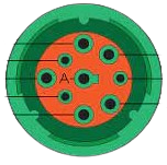
Pin Configuration and Descriptions
SAE J1939 uses a standard 9-pin Deutsch connector (commonly referred to as the J1939-13 connector). Below is the pinout:
| Pin | Signal Name | Description |
|---|---|---|
| 1 | Battery (-) | Ground connection |
| 2 | Battery (+) | Power supply (12V or 24V) |
| 3 | CAN High (CAN_H) | CAN bus high line |
| 4 | Reserved | Reserved for future use |
| 5 | CAN Shield | Shielding for CAN bus |
| 6 | CAN Low (CAN_L) | CAN bus low line |
| 7 | Reserved | Reserved for future use |
| 8 | Reserved | Reserved for future use |
| 9 | CAN Shield | Additional shielding for CAN bus |
Usage Instructions
How to Use SAE J1939 in a Circuit
- Connect the CAN Bus: Use a CAN transceiver to interface the SAE J1939 network with your microcontroller or ECU. Ensure proper connections to the CAN_H and CAN_L lines.
- Power the System: Provide a stable 12V or 24V power supply to the J1939 connector.
- Address Configuration: Assign a unique 8-bit address to each device on the network. Avoid address conflicts.
- Message Transmission: Use the 29-bit identifier to structure messages. Ensure compliance with the J1939 protocol for data formatting.
- Termination Resistors: Place 120-ohm termination resistors at both ends of the CAN bus to prevent signal reflections.
Important Considerations and Best Practices
- Shielding: Use shielded twisted-pair cables to minimize electromagnetic interference (EMI).
- Termination: Always use proper termination resistors to maintain signal integrity.
- Error Handling: Implement error-handling routines to detect and recover from communication errors.
- Address Management: Use dynamic address claiming (as defined in J1939-81) to avoid conflicts in multi-device networks.
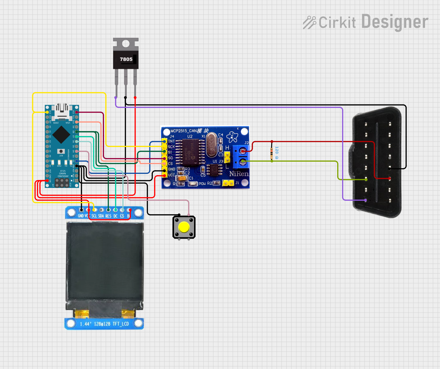
Example: Connecting SAE J1939 to an Arduino UNO
Below is an example of how to interface an Arduino UNO with an SAE J1939 network using an MCP2515 CAN module:
#include <SPI.h>
#include <mcp_can.h>

// Define the SPI CS pin for the MCP2515 CAN module
#define CAN_CS_PIN 10

// Initialize the MCP_CAN object
MCP_CAN CAN(CAN_CS_PIN);

void setup() {
  Serial.begin(115200);
  while (!Serial);

  // Initialize the CAN bus at 250 kbps (standard for SAE J1939)
  if (CAN.begin(MCP_ANY, 250000, MCP_8MHZ) == CAN_OK) {
    Serial.println("CAN bus initialized successfully!");
  } else {
    Serial.println("Error initializing CAN bus.");
    while (1);
  }

  // Set the CAN bus to normal mode
  CAN.setMode(MCP_NORMAL);
  Serial.println("CAN bus set to normal mode.");
}

void loop() {
  // Example: Send a J1939 message with a 29-bit identifier
  unsigned long id = 0x18FF50E5; // Example J1939 PGN and source address
  byte data[8] = {0x01, 0x02, 0x03, 0x04, 0x05, 0x06, 0x07, 0x08};

  if (CAN.sendMsgBuf(id, 1, 8, data) == CAN_OK) {
    Serial.println("Message sent successfully!");
  } else {
    Serial.println("Error sending message.");
  }

  delay(1000); // Wait 1 second before sending the next message
}
Notes:
- Ensure the MCP2515 CAN module is properly connected to the Arduino UNO.
- Use a 120-ohm termination resistor at both ends of the CAN bus.
- Replace the
idanddatavalues with appropriate values for your application.
Troubleshooting and FAQs
Common Issues and Solutions
No Communication on the CAN Bus
- Cause: Missing or incorrect termination resistors.
- Solution: Verify that 120-ohm resistors are installed at both ends of the CAN bus.
Address Conflicts
- Cause: Two devices on the network have the same address.
- Solution: Use dynamic address claiming or manually assign unique addresses.
High Error Rates
- Cause: Poor cable shielding or excessive cable length.
- Solution: Use shielded twisted-pair cables and keep the total bus length within the recommended limits.
Power Supply Issues
- Cause: Insufficient or unstable power supply.
- Solution: Ensure a stable 12V or 24V power source with adequate current capacity.
FAQs
Q: Can SAE J1939 be used with 500 kbps CAN networks?
A: Yes, while 250 kbps is the standard, some applications support 500 kbps. Ensure all devices on the network are configured for the same data rate.
Q: How many devices can be connected to an SAE J1939 network?
A: Up to 30 devices can typically be connected, but this depends on the specific implementation and network load.
Q: Is SAE J1939 compatible with standard CAN protocols?
A: SAE J1939 is built on the CAN protocol but uses a specific 29-bit identifier format and additional protocol layers. Compatibility depends on the implementation.