
How to Use ID-12 125 kHz RFID Reader: Examples, Pinouts, and Specs

 Design with ID-12 125 kHz RFID Reader in Cirkit Designer
Introduction
The ID-12 RFID Reader, manufactured by ID Innovations, is a compact and efficient RFID module designed to operate at a frequency of 125 kHz. It is capable of reading passive RFID tags and transmitting the tag data via a serial interface. This module is widely used in applications such as access control systems, inventory management, time tracking, and other identification-based systems. Its small size, ease of integration, and reliable performance make it a popular choice for both hobbyists and professionals.
Explore Projects Built with ID-12 125 kHz RFID Reader
 Open Project in Cirkit Designer
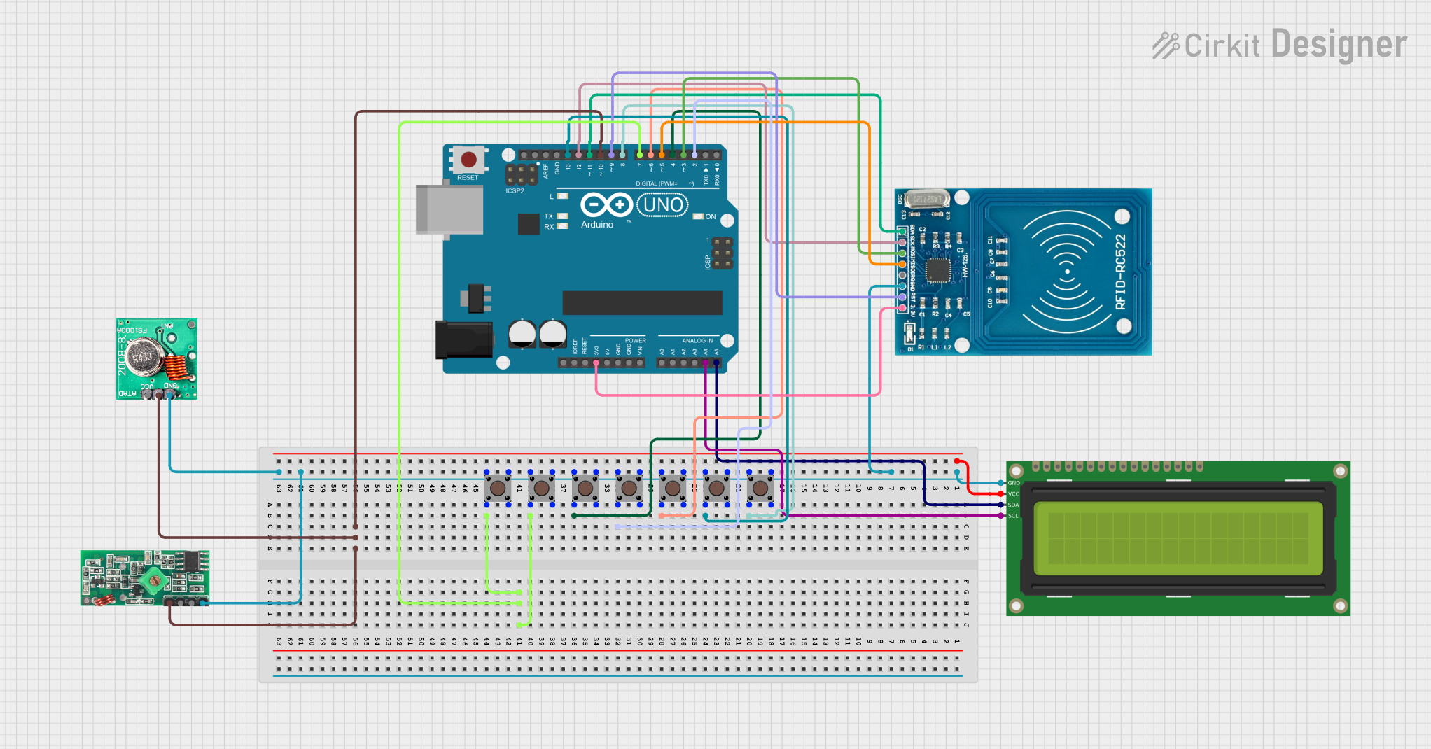 Open Project in Cirkit Designer
 Open Project in Cirkit Designer
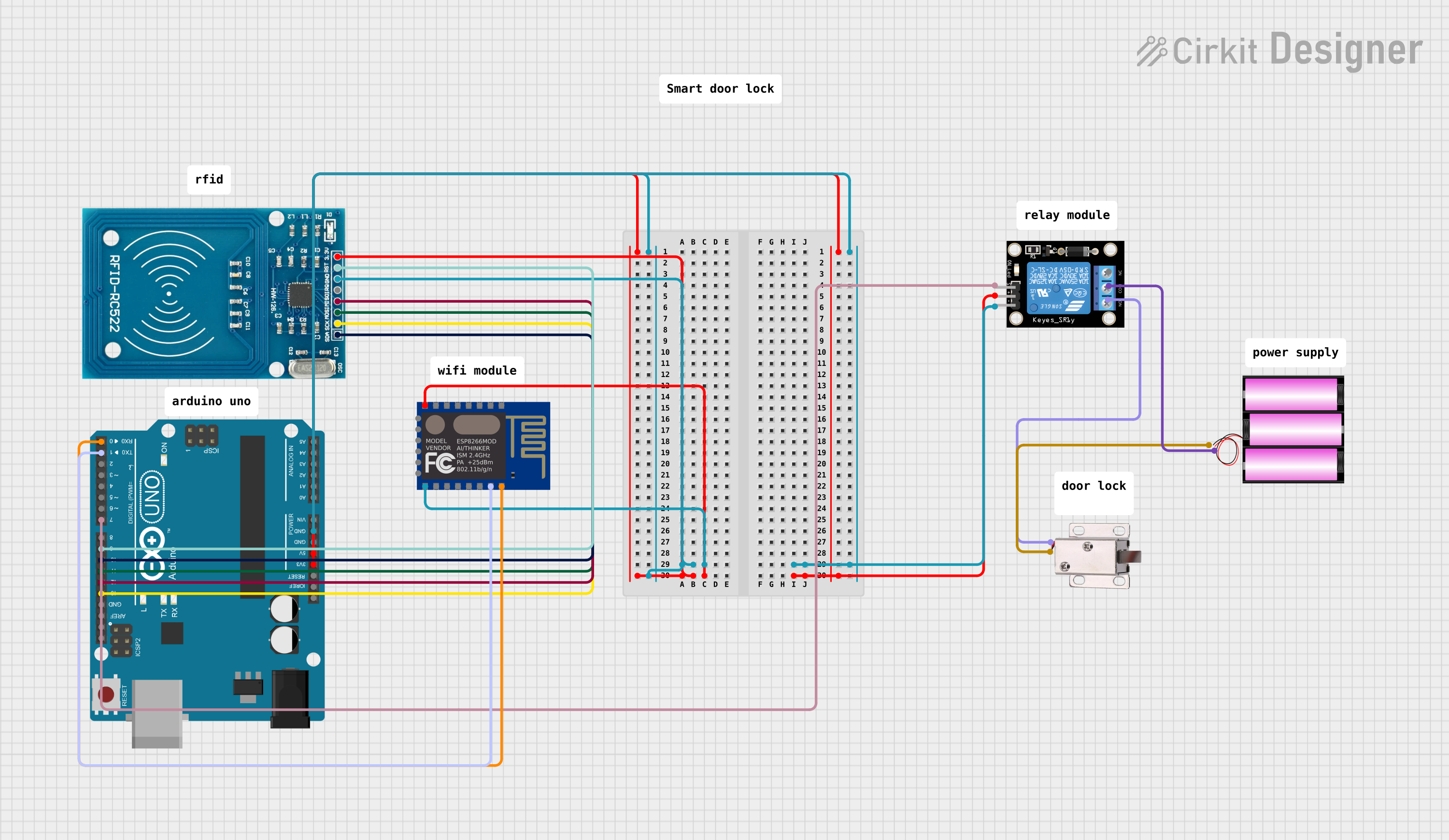 Open Project in Cirkit Designer
Explore Projects Built with ID-12 125 kHz RFID Reader
Open Project in Cirkit DesignerOpen Project in Cirkit DesignerOpen Project in Cirkit DesignerOpen Project in Cirkit DesignerTechnical Specifications
The following table outlines the key technical specifications of the ID-12 RFID Reader:
| Parameter | Specification |
|---|---|
| Operating Frequency | 125 kHz |
| Operating Voltage | 4.6V to 5.4V |
| Current Consumption | 15 mA (typical) |
| Communication Interface | UART (Serial) |
| Baud Rate | 9600 bps |
| Read Range | Up to 12 cm (depending on tag) |
| Supported Tag Types | EM4100 family |
| Dimensions | 25 mm x 26 mm x 7 mm |
| Operating Temperature | -30°C to +85°C |
Pin Configuration and Descriptions
The ID-12 RFID Reader has a 12-pin interface. The table below describes each pin:
| Pin Number | Pin Name | Description |
|---|---|---|
| 1 | GND | Ground |
| 2 | VCC | Power supply input (4.6V to 5.4V) |
| 3 | /RESET | Active low reset input |
| 4 | D0 | Data output (Wiegand protocol) |
| 5 | D1 | Data output (Wiegand protocol) |
| 6 | NC | Not connected |
| 7 | FORMAT | Selects data output format |
| 8 | BEEP/LED | Controls the onboard LED and buzzer |
| 9 | GND | Ground |
| 10 | TX | Serial data output (UART) |
| 11 | RX | Serial data input (UART) |
| 12 | ANT | Antenna connection (internal use) |
Usage Instructions
How to Use the ID-12 RFID Reader in a Circuit
- Power Supply: Connect the
VCCpin to a 5V power source and theGNDpin to ground. - Serial Communication: Use the
TXpin to transmit data to a microcontroller or computer. TheRXpin can be used for receiving commands if needed. - Reset: Optionally, connect the
/RESETpin to a microcontroller or a push button for resetting the module. - Data Format: Use the
FORMATpin to select the desired data output format. Refer to the manufacturer's datasheet for specific format configurations. - Buzzer and LED: The
BEEP/LEDpin can be used to control the onboard buzzer and LED for visual and audible feedback.
Important Considerations and Best Practices
- Ensure the power supply voltage is within the specified range (4.6V to 5.4V) to avoid damaging the module.
- Place the RFID reader away from metal surfaces or other sources of electromagnetic interference to maximize the read range.
- Use a decoupling capacitor (e.g., 10 µF) between
VCCandGNDto stabilize the power supply. - When connecting to a microcontroller, ensure the UART baud rate is set to 9600 bps for proper communication.
Example: Connecting the ID-12 to an Arduino UNO
Below is an example of how to connect the ID-12 RFID Reader to an Arduino UNO and read RFID tag data:
Wiring Diagram
| ID-12 Pin | Arduino Pin |
|---|---|
| VCC | 5V |
| GND | GND |
| TX | D2 |
Arduino Code
// Example code for interfacing the ID-12 RFID Reader with Arduino UNO
// Connect the TX pin of the ID-12 to Arduino digital pin 2

#include <SoftwareSerial.h>

// Define RX and TX pins for SoftwareSerial
SoftwareSerial rfidReader(2, 3); // RX = pin 2, TX = pin 3 (TX not used here)

void setup() {
  Serial.begin(9600); // Initialize hardware serial for debugging
  rfidReader.begin(9600); // Initialize software serial for ID-12 communication
  Serial.println("ID-12 RFID Reader Ready");
}

void loop() {
  // Check if data is available from the RFID reader
  if (rfidReader.available()) {
    String tagData = ""; // Variable to store the tag data

    // Read data from the RFID reader
    while (rfidReader.available()) {
      char c = rfidReader.read(); // Read one character at a time
      tagData += c; // Append character to the tag data string
    }

    // Print the tag data to the Serial Monitor
    Serial.print("RFID Tag Data: ");
    Serial.println(tagData);
  }
}
Troubleshooting and FAQs
Common Issues and Solutions
No Data Output:
- Ensure the
TXpin of the ID-12 is properly connected to the RX pin of the microcontroller. - Verify that the power supply voltage is within the specified range (4.6V to 5.4V).
- Check the baud rate configuration. It should be set to 9600 bps.
- Ensure the
Short Read Range:
- Ensure there are no metal objects or electromagnetic interference near the RFID reader.
- Use high-quality RFID tags that are compatible with the EM4100 standard.
Module Not Responding:
- Check the
/RESETpin. Ensure it is not held low unintentionally. - Verify all connections and ensure the module is powered correctly.
- Check the
FAQs
Q: What type of RFID tags are compatible with the ID-12?
A: The ID-12 is compatible with passive RFID tags that follow the EM4100 standard.
Q: Can the ID-12 read multiple tags simultaneously?
A: No, the ID-12 can only read one tag at a time.
Q: How can I increase the read range of the ID-12?
A: The read range is primarily determined by the tag and environmental factors. Use high-quality tags and minimize interference to achieve the maximum range of up to 12 cm.
Q: Is the ID-12 suitable for outdoor use?
A: The ID-12 can operate in temperatures ranging from -30°C to +85°C, but it should be protected from moisture and direct exposure to harsh environmental conditions.