Cirkit Designer Logo
Cirkit Designer
Your all-in-one circuit design IDE
Home / 
Component Documentation

How to Use ESP32 DevKit V1 (CP2102): Examples, Pinouts, and Specs

Image of ESP32 DevKit V1 (CP2102)
Cirkit Designer LogoDesign with ESP32 DevKit V1 (CP2102) in Cirkit Designer

Introduction

The ESP32 DevKit V1 (CP2102) is a versatile development board based on the ESP32-WROOM-32 module. It features dual-core processing, integrated Wi-Fi, and Bluetooth capabilities, making it an excellent choice for Internet of Things (IoT) applications, smart devices, and wireless communication projects. The board includes a CP2102 USB-to-UART bridge, simplifying programming and serial communication with a computer.

Explore Projects Built with ESP32 DevKit V1 (CP2102)

Use Cirkit Designer to design, explore, and prototype these projects online. Some projects support real-time simulation. Click "Open Project" to start designing instantly!
ESP32 and Logic Level Converter-Based Wi-Fi Controlled Interface
Image of Toshiba AC ESP32 devkit v1: A project utilizing ESP32 DevKit V1 (CP2102) in a practical application
This circuit features an ESP32 Devkit V1 microcontroller connected to a Bi-Directional Logic Level Converter, which facilitates voltage level shifting between the ESP32 and external components. The ESP32 is powered through its VIN pin via an alligator clip cable, and the logic level converter is connected to various pins on the ESP32 to manage different voltage levels for communication.
Cirkit Designer LogoOpen Project in Cirkit Designer
ESP32-Based Environmental Monitoring System with Water Flow Sensing
Image of Water: A project utilizing ESP32 DevKit V1 (CP2102) in a practical application
This circuit features an ESP32 Devkit V1 microcontroller connected to a DHT22 temperature and humidity sensor and a water flow sensor. The ESP32 reads environmental data from the DHT22 via a digital input pin (D33) and monitors water flow through the water flow sensor connected to another digital input pin (D23). The ESP32 is powered through its VIN pin, and both sensors are powered by the ESP32's 3V3 output, with common ground connections.
Cirkit Designer LogoOpen Project in Cirkit Designer
ESP32-Based Smart Agriculture System with LoRa Communication
Image of Soil Monitoring Device: A project utilizing ESP32 DevKit V1 (CP2102) in a practical application
This circuit features an ESP32 Devkit V1 microcontroller as the central processing unit, interfacing with various sensors including a PH Meter, an NPK Soil Sensor, and a Soil Moisture Sensor for environmental data collection. It also includes an EBYTE LoRa E220 module for wireless communication. Power management is handled by a Step Up Boost Power Converter, which is connected to a 12V Battery, stepping up the voltage to power the ESP32 and sensors, with common ground connections throughout the circuit.
Cirkit Designer LogoOpen Project in Cirkit Designer
ESP32-Based Environmental Monitoring and Alert System with Solar Charging
Image of mark: A project utilizing ESP32 DevKit V1 (CP2102) in a practical application
This circuit features an ESP32 Devkit V1 microcontroller connected to various sensors and modules for monitoring and communication purposes. It includes an MQ-2 gas sensor and a DHT11 temperature and humidity sensor, both interfaced with the ESP32 for environmental data collection. The circuit is powered by a 12V battery, regulated to 5V by step-down converters, and includes a solar charge controller connected to a solar panel for battery charging, a UPS module for power management, and a SIM900A module for GSM communication. Additionally, there is a WS2812 RGB LED strip for visual feedback and a piezo buzzer for audio alerts, both controlled by the ESP32.
Cirkit Designer LogoOpen Project in Cirkit Designer

Explore Projects Built with ESP32 DevKit V1 (CP2102)

Use Cirkit Designer to design, explore, and prototype these projects online. Some projects support real-time simulation. Click "Open Project" to start designing instantly!
Image of Toshiba AC ESP32 devkit v1: A project utilizing ESP32 DevKit V1 (CP2102) in a practical application
ESP32 and Logic Level Converter-Based Wi-Fi Controlled Interface
This circuit features an ESP32 Devkit V1 microcontroller connected to a Bi-Directional Logic Level Converter, which facilitates voltage level shifting between the ESP32 and external components. The ESP32 is powered through its VIN pin via an alligator clip cable, and the logic level converter is connected to various pins on the ESP32 to manage different voltage levels for communication.
Cirkit Designer LogoOpen Project in Cirkit Designer
Image of Water: A project utilizing ESP32 DevKit V1 (CP2102) in a practical application
ESP32-Based Environmental Monitoring System with Water Flow Sensing
This circuit features an ESP32 Devkit V1 microcontroller connected to a DHT22 temperature and humidity sensor and a water flow sensor. The ESP32 reads environmental data from the DHT22 via a digital input pin (D33) and monitors water flow through the water flow sensor connected to another digital input pin (D23). The ESP32 is powered through its VIN pin, and both sensors are powered by the ESP32's 3V3 output, with common ground connections.
Cirkit Designer LogoOpen Project in Cirkit Designer
Image of Soil Monitoring Device: A project utilizing ESP32 DevKit V1 (CP2102) in a practical application
ESP32-Based Smart Agriculture System with LoRa Communication
This circuit features an ESP32 Devkit V1 microcontroller as the central processing unit, interfacing with various sensors including a PH Meter, an NPK Soil Sensor, and a Soil Moisture Sensor for environmental data collection. It also includes an EBYTE LoRa E220 module for wireless communication. Power management is handled by a Step Up Boost Power Converter, which is connected to a 12V Battery, stepping up the voltage to power the ESP32 and sensors, with common ground connections throughout the circuit.
Cirkit Designer LogoOpen Project in Cirkit Designer
Image of mark: A project utilizing ESP32 DevKit V1 (CP2102) in a practical application
ESP32-Based Environmental Monitoring and Alert System with Solar Charging
This circuit features an ESP32 Devkit V1 microcontroller connected to various sensors and modules for monitoring and communication purposes. It includes an MQ-2 gas sensor and a DHT11 temperature and humidity sensor, both interfaced with the ESP32 for environmental data collection. The circuit is powered by a 12V battery, regulated to 5V by step-down converters, and includes a solar charge controller connected to a solar panel for battery charging, a UPS module for power management, and a SIM900A module for GSM communication. Additionally, there is a WS2812 RGB LED strip for visual feedback and a piezo buzzer for audio alerts, both controlled by the ESP32.
Cirkit Designer LogoOpen Project in Cirkit Designer

Common Applications and Use Cases

  • IoT devices and smart home automation
  • Wireless sensor networks
  • Bluetooth Low Energy (BLE) applications
  • Real-time data monitoring and logging
  • Robotics and embedded systems
  • Prototyping and development of wireless communication systems

Technical Specifications

Key Technical Details

Parameter Specification
Microcontroller ESP32-WROOM-32
Processor Dual-core Xtensa® 32-bit LX6
Clock Speed Up to 240 MHz
Flash Memory 4 MB
SRAM 520 KB
Wi-Fi 802.11 b/g/n
Bluetooth v4.2 BR/EDR and BLE
Operating Voltage 3.3V
Input Voltage (via USB) 5V
GPIO Pins 30
ADC Channels 18
DAC Channels 2
Communication Interfaces UART, SPI, I2C, I2S, CAN, PWM
USB-to-UART Bridge CP2102
Dimensions 54 mm x 27 mm

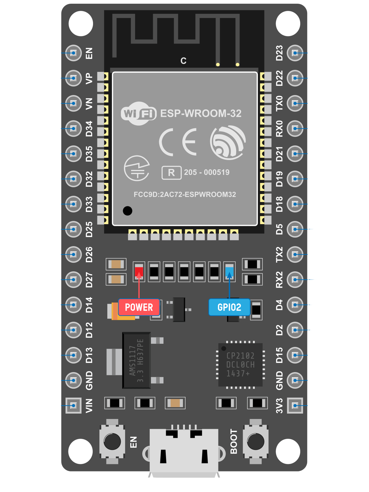
Pin Configuration and Descriptions

The ESP32 DevKit V1 has 30 GPIO pins, many of which are multifunctional. Below is a table of the most commonly used pins and their functions:

Pin Number Pin Name Functionality
1 EN Reset the chip (active high)
2 GPIO0 Boot mode selection, general-purpose I/O
3 GPIO2 General-purpose I/O, ADC2 channel
4 GPIO4 General-purpose I/O, ADC2 channel
5 GPIO5 General-purpose I/O, ADC2 channel, PWM
6 GPIO12 General-purpose I/O, ADC2 channel, PWM
7 GPIO13 General-purpose I/O, ADC2 channel, PWM
8 GPIO14 General-purpose I/O, ADC2 channel, PWM
9 GPIO15 General-purpose I/O, ADC2 channel, PWM
10 GPIO16 General-purpose I/O, ADC2 channel
11 GPIO17 General-purpose I/O, ADC2 channel
12 GPIO18 SPI clock (SCK), general-purpose I/O
13 GPIO19 SPI MISO, general-purpose I/O
14 GPIO21 I2C SDA, general-purpose I/O
15 GPIO22 I2C SCL, general-purpose I/O
16 GPIO23 SPI MOSI, general-purpose I/O
17 GPIO25 DAC1, ADC2 channel, general-purpose I/O
18 GPIO26 DAC2, ADC2 channel, general-purpose I/O
19 GPIO27 ADC2 channel, general-purpose I/O
20 GPIO32 ADC1 channel, general-purpose I/O
21 GPIO33 ADC1 channel, general-purpose I/O
22 GPIO34 ADC1 channel (input only)
23 GPIO35 ADC1 channel (input only)
24 GPIO36 ADC1 channel (input only)
25 GPIO39 ADC1 channel (input only)

Usage Instructions

How to Use the ESP32 DevKit V1 in a Circuit

  1. Powering the Board:

    • Connect the board to your computer using a micro-USB cable. The CP2102 USB-to-UART bridge will handle communication and power the board.
    • Alternatively, you can power the board via the 3.3V or 5V pins.
  2. Programming the Board:

    • Install the CP2102 driver on your computer (if not already installed).
    • Use the Arduino IDE or ESP-IDF (Espressif IoT Development Framework) to write and upload code to the ESP32.
    • Select the correct board (ESP32 Dev Module) and port in the Arduino IDE.
  3. Connecting Peripherals:

    • Use the GPIO pins to connect sensors, actuators, or other peripherals.
    • Ensure that the voltage levels of connected devices are compatible with the ESP32 (3.3V logic).
  4. Flashing Code:

    • Hold the BOOT button while uploading code to put the ESP32 into flashing mode.
    • Release the BOOT button once the upload begins.

Important Considerations and Best Practices

  • Avoid connecting 5V logic devices directly to the GPIO pins, as the ESP32 operates at 3.3V logic levels.
  • Use level shifters if interfacing with 5V devices.
  • Do not exceed the maximum current rating of the GPIO pins (12 mA per pin).
  • Use decoupling capacitors near the power pins to reduce noise in sensitive applications.

Example Code for Arduino UNO Integration

Below is an example of how to use the ESP32 DevKit V1 to blink an LED connected to GPIO2:

// Define the GPIO pin for the LED
#define LED_PIN 2

void setup() {
  // Set the LED pin as an output
  pinMode(LED_PIN, OUTPUT);
}

void loop() {
  // Turn the LED on
  digitalWrite(LED_PIN, HIGH);
  delay(1000); // Wait for 1 second

  // Turn the LED off
  digitalWrite(LED_PIN, LOW);
  delay(1000); // Wait for 1 second
}

Troubleshooting and FAQs

Common Issues and Solutions

  1. ESP32 Not Detected by Computer:

    • Ensure the CP2102 driver is installed correctly.
    • Try a different USB cable or port.
  2. Code Upload Fails:

    • Check that the correct board and port are selected in the Arduino IDE.
    • Hold the BOOT button while uploading the code.
  3. Wi-Fi Connection Issues:

    • Verify the SSID and password in your code.
    • Ensure the Wi-Fi network is within range and operational.
  4. GPIO Pin Not Working:

    • Confirm that the pin is not being used for another function (e.g., boot mode).
    • Check for short circuits or incorrect wiring.

FAQs

Q: Can I power the ESP32 DevKit V1 with a battery?
A: Yes, you can power the board using a 3.7V LiPo battery connected to the 3.3V pin or a 5V source connected to the 5V pin.

Q: What is the maximum Wi-Fi range of the ESP32?
A: The range depends on environmental factors but typically extends up to 100 meters in open spaces.

Q: Can I use the ESP32 DevKit V1 for Bluetooth audio streaming?
A: Yes, the ESP32 supports Bluetooth audio streaming using the A2DP profile.

Q: How do I reset the ESP32?
A: Press the EN button to reset the board.

This concludes the documentation for the ESP32 DevKit V1 (CP2102).