How to Use motor driver xymc10: Examples, Pinouts, and Specs
Introduction
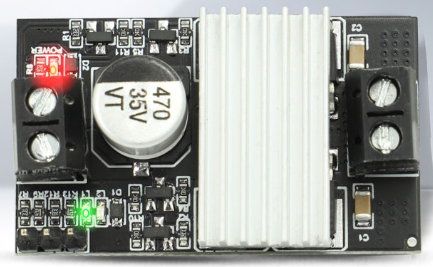
The XYMC10 is a versatile motor driver designed to control both DC motors and stepper motors with precision and efficiency. It features adjustable current control, thermal protection, and supports multiple control modes, including PWM (Pulse Width Modulation) and direction control. These features make the XYMC10 an ideal choice for robotics, automation systems, and other motor control applications.
Explore Projects Built with motor driver xymc10


Explore Projects Built with motor driver xymc10
Common Applications and Use Cases
- Robotics and mechatronics projects
- Conveyor belt systems
- Automated guided vehicles (AGVs)
- CNC machines and 3D printers
- Home automation systems involving motorized components
Technical Specifications
Key Technical Details
| Parameter | Value |
|---|---|
| Operating Voltage Range | 6V to 36V |
| Maximum Output Current | 2A per channel (continuous) |
| Peak Output Current | 3A per channel (for short bursts) |
| Control Modes | PWM, Direction, and Enable |
| Thermal Protection | Built-in thermal shutdown |
| Current Control | Adjustable via onboard potentiometer |
| Supported Motors | DC motors, Bipolar stepper motors |
| Operating Temperature Range | -20°C to 85°C |
Pin Configuration and Descriptions
The XYMC10 has a total of 8 pins for interfacing. Below is the pinout and description:
| Pin Number | Pin Name | Description |
|---|---|---|
| 1 | VCC | Power supply input (6V to 36V) |
| 2 | GND | Ground connection |
| 3 | IN1 | Input signal for controlling motor direction (Channel 1) |
| 4 | IN2 | Input signal for controlling motor direction (Channel 2) |
| 5 | ENA | Enable pin for Channel 1 (PWM signal can be applied here for speed control) |
| 6 | ENB | Enable pin for Channel 2 (PWM signal can be applied here for speed control) |
| 7 | OUT1 | Output to motor terminal 1 (Channel 1) |
| 8 | OUT2 | Output to motor terminal 2 (Channel 2) |
Usage Instructions
How to Use the XYMC10 in a Circuit
- Power Supply: Connect the VCC pin to a power source within the range of 6V to 36V. Ensure the power supply can provide sufficient current for the motors.
- Motor Connections: Connect the motor terminals to the OUT1 and OUT2 pins for Channel 1. For dual-motor setups, use the corresponding pins for Channel 2.
- Control Signals:
- Use the IN1 and IN2 pins to control the direction of the motor. For example:
- IN1 = HIGH, IN2 = LOW: Motor rotates forward.
- IN1 = LOW, IN2 = HIGH: Motor rotates backward.
- Apply a PWM signal to the ENA or ENB pins to control motor speed.
- Use the IN1 and IN2 pins to control the direction of the motor. For example:
- Adjust Current Limit: Use the onboard potentiometer to set the desired current limit for the motors. This helps prevent motor overheating or damage.
- Thermal Protection: The XYMC10 includes built-in thermal shutdown. Ensure proper ventilation or heat dissipation to avoid triggering this protection.
Important Considerations and Best Practices
- Always verify the motor's voltage and current ratings to ensure compatibility with the XYMC10.
- Use decoupling capacitors near the VCC pin to reduce noise and voltage spikes.
- Avoid exceeding the maximum current rating (2A continuous, 3A peak) to prevent damage to the driver.
- For stepper motors, ensure proper sequencing of control signals to achieve smooth operation.
Example: Using XYMC10 with Arduino UNO
Below is an example of controlling a DC motor using the XYMC10 and an Arduino UNO:
// Define control pins for the XYMC10 motor driver
const int IN1 = 9;  // Direction control pin for Channel 1
const int IN2 = 10; // Direction control pin for Channel 1
const int ENA = 11; // PWM speed control pin for Channel 1

void setup() {
  // Set motor driver pins as outputs
  pinMode(IN1, OUTPUT);
  pinMode(IN2, OUTPUT);
  pinMode(ENA, OUTPUT);
}

void loop() {
  // Rotate motor forward at 50% speed
  digitalWrite(IN1, HIGH);  // Set IN1 HIGH
  digitalWrite(IN2, LOW);   // Set IN2 LOW
  analogWrite(ENA, 128);    // Set PWM duty cycle to 50% (128 out of 255)
  delay(2000);              // Run motor for 2 seconds

  // Rotate motor backward at 75% speed
  digitalWrite(IN1, LOW);   // Set IN1 LOW
  digitalWrite(IN2, HIGH);  // Set IN2 HIGH
  analogWrite(ENA, 192);    // Set PWM duty cycle to 75% (192 out of 255)
  delay(2000);              // Run motor for 2 seconds

  // Stop the motor
  digitalWrite(IN1, LOW);   // Set IN1 LOW
  digitalWrite(IN2, LOW);   // Set IN2 LOW
  analogWrite(ENA, 0);      // Set PWM duty cycle to 0% (motor off)
  delay(2000);              // Wait for 2 seconds before repeating
}
Troubleshooting and FAQs
Common Issues and Solutions
Motor Not Spinning:
- Cause: Incorrect wiring or insufficient power supply.
- Solution: Double-check all connections and ensure the power supply meets the voltage and current requirements.
Motor Spins in the Wrong Direction:
- Cause: IN1 and IN2 signals are reversed.
- Solution: Swap the HIGH/LOW signals on IN1 and IN2 to correct the direction.
Motor Stalls or Overheats:
- Cause: Current limit is set too low or motor is overloaded.
- Solution: Adjust the current limit using the potentiometer and ensure the motor is not overloaded.
Driver Overheats and Shuts Down:
- Cause: Prolonged operation at high current or insufficient cooling.
- Solution: Improve ventilation or add a heatsink to the driver.
FAQs
Can the XYMC10 drive two motors simultaneously? Yes, the XYMC10 has two channels and can control two DC motors independently.
Is the XYMC10 compatible with stepper motors? Yes, the XYMC10 supports bipolar stepper motors. Ensure proper sequencing of control signals.
What happens if the current exceeds the limit? The XYMC10 includes thermal protection and will shut down temporarily to prevent damage.
Can I use the XYMC10 with a 5V logic microcontroller? Yes, the XYMC10 is compatible with 5V logic levels for control signals.