Cirkit Designer Logo
Cirkit Designer
Your all-in-one circuit design IDE
Home / 
Component Documentation

How to Use lm2596 Step-Down Buck DC/DC: Examples, Pinouts, and Specs

Image of lm2596 Step-Down Buck DC/DC
Cirkit Designer LogoDesign with lm2596 Step-Down Buck DC/DC in Cirkit Designer

Introduction

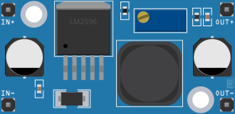
The LM2596 is a high-efficiency step-down (buck) DC/DC voltage regulator designed to convert a higher DC input voltage into a stable, lower DC output voltage. Manufactured by CN China, this component is widely used in applications requiring efficient power conversion with minimal heat generation. Its compact design and integrated features make it ideal for powering microcontrollers, sensors, and other low-voltage devices.

Explore Projects Built with lm2596 Step-Down Buck DC/DC

Use Cirkit Designer to design, explore, and prototype these projects online. Some projects support real-time simulation. Click "Open Project" to start designing instantly!
Voltage Regulation System with MT3608 Boost and LM2596 Buck Converters
Image of solar system router ups: A project utilizing lm2596 Step-Down Buck DC/DC in a practical application
This circuit consists of two MT3608 boost converters and an LM2596 step-down module, each connected to separate 12V power supplies. The MT3608 modules are configured to step up the voltage from their respective power supplies, while the LM2596 module steps down the voltage from a 12V battery. Diodes are used to ensure correct current flow direction, potentially for protection or isolation between different parts of the circuit.
Cirkit Designer LogoOpen Project in Cirkit Designer
Battery-Powered DC Generator with XL4015 Buck Converter
Image of conveyor: A project utilizing lm2596 Step-Down Buck DC/DC in a practical application
This circuit consists of a 12V battery connected to a rocker switch, which controls the input to an XL4015 DC Buck Step-down converter. The converter steps down the voltage to power a DC generator, with the generator's output connected back to the converter to form a feedback loop.
Cirkit Designer LogoOpen Project in Cirkit Designer
Dual Motor Control Circuit with Directional Switching and Voltage Regulation
Image of Pencuci Kipas: A project utilizing lm2596 Step-Down Buck DC/DC in a practical application
This circuit features a 12V battery connected through a rocker switch to two buck converters, one of which steps down the voltage to power two DC mini metal gear motors, and the other is connected to a directional switch that controls a third DC mini metal gear motor. The XL4015 5A DC Buck Step-down converter's output is connected to two motors, allowing them to run at a reduced voltage, while the other buck converter's output is routed through a directional switch to control the direction of the third motor.
Cirkit Designer LogoOpen Project in Cirkit Designer
Battery-Powered ESP32 Devkit V1 with Buck Converter and Switch Control
Image of Autonomus Car: A project utilizing lm2596 Step-Down Buck DC/DC in a practical application
This circuit is a power management system that uses two 18650 Li-ion batteries to supply power through a toggle switch and a rocker switch to an LM2956 Buck Converter. The buck converter steps down the voltage to a suitable level for a connected device via a Micro USB cable.
Cirkit Designer LogoOpen Project in Cirkit Designer

Explore Projects Built with lm2596 Step-Down Buck DC/DC

Use Cirkit Designer to design, explore, and prototype these projects online. Some projects support real-time simulation. Click "Open Project" to start designing instantly!
Image of solar system router ups: A project utilizing lm2596 Step-Down Buck DC/DC in a practical application
Voltage Regulation System with MT3608 Boost and LM2596 Buck Converters
This circuit consists of two MT3608 boost converters and an LM2596 step-down module, each connected to separate 12V power supplies. The MT3608 modules are configured to step up the voltage from their respective power supplies, while the LM2596 module steps down the voltage from a 12V battery. Diodes are used to ensure correct current flow direction, potentially for protection or isolation between different parts of the circuit.
Cirkit Designer LogoOpen Project in Cirkit Designer
Image of conveyor: A project utilizing lm2596 Step-Down Buck DC/DC in a practical application
Battery-Powered DC Generator with XL4015 Buck Converter
This circuit consists of a 12V battery connected to a rocker switch, which controls the input to an XL4015 DC Buck Step-down converter. The converter steps down the voltage to power a DC generator, with the generator's output connected back to the converter to form a feedback loop.
Cirkit Designer LogoOpen Project in Cirkit Designer
Image of Pencuci Kipas: A project utilizing lm2596 Step-Down Buck DC/DC in a practical application
Dual Motor Control Circuit with Directional Switching and Voltage Regulation
This circuit features a 12V battery connected through a rocker switch to two buck converters, one of which steps down the voltage to power two DC mini metal gear motors, and the other is connected to a directional switch that controls a third DC mini metal gear motor. The XL4015 5A DC Buck Step-down converter's output is connected to two motors, allowing them to run at a reduced voltage, while the other buck converter's output is routed through a directional switch to control the direction of the third motor.
Cirkit Designer LogoOpen Project in Cirkit Designer
Image of Autonomus Car: A project utilizing lm2596 Step-Down Buck DC/DC in a practical application
Battery-Powered ESP32 Devkit V1 with Buck Converter and Switch Control
This circuit is a power management system that uses two 18650 Li-ion batteries to supply power through a toggle switch and a rocker switch to an LM2956 Buck Converter. The buck converter steps down the voltage to a suitable level for a connected device via a Micro USB cable.
Cirkit Designer LogoOpen Project in Cirkit Designer

Common Applications

  • Powering microcontrollers (e.g., Arduino, Raspberry Pi)
  • Battery-powered systems
  • LED drivers
  • Industrial automation
  • Consumer electronics
  • DIY electronics projects

Technical Specifications

The LM2596 is a versatile component with the following key specifications:

Parameter Value
Input Voltage Range 4.5V to 40V
Output Voltage Range 1.23V to 37V (adjustable)
Output Current Up to 3A
Efficiency Up to 92%
Switching Frequency 150 kHz
Operating Temperature -40°C to +125°C
Package Type TO-220 or TO-263

Pin Configuration and Descriptions

The LM2596 typically comes in a 5-pin package. Below is the pinout and description:

Pin Number Pin Name Description
1 VIN Input voltage (4.5V to 40V)
2 Output Regulated output voltage (1.23V to 37V)
3 Ground (GND) Ground connection
4 Feedback Voltage feedback pin for output voltage regulation
5 ON/OFF Enable/disable pin (active low)

Usage Instructions

How to Use the LM2596 in a Circuit

  1. Connect the Input Voltage (VIN):

    • Attach the positive terminal of the input power supply to the VIN pin.
    • Connect the negative terminal of the power supply to the GND pin.
  2. Set the Output Voltage:

    • Use an external resistor divider network connected to the Feedback pin to set the desired output voltage.
    • The output voltage can be calculated using the formula:
      [ V_{OUT} = V_{REF} \times \left(1 + \frac{R1}{R2}\right) ]
      where ( V_{REF} ) is 1.23V.
  3. Connect the Load:

    • Attach the positive terminal of the load to the Output pin.
    • Connect the negative terminal of the load to the GND pin.
  4. Enable the Regulator (Optional):

    • If the ON/OFF pin is used, connect it to GND to enable the regulator.
    • Leave it floating or connect it to VIN to disable the regulator.

Important Considerations and Best Practices

  • Input Capacitor: Place a low-ESR capacitor (e.g., 100 µF) close to the VIN pin to stabilize the input voltage.
  • Output Capacitor: Use a low-ESR capacitor (e.g., 220 µF) at the output to reduce voltage ripple.
  • Inductor Selection: Choose an inductor with a current rating higher than the maximum load current and a suitable inductance value (e.g., 33 µH).
  • Heat Dissipation: Ensure proper heat sinking or airflow to prevent overheating, especially at high currents.
  • Avoid Overloading: Do not exceed the maximum output current of 3A to prevent damage.

Example: Using LM2596 with Arduino UNO

Below is an example of how to use the LM2596 to power an Arduino UNO with a 12V input and a 5V output:

Circuit Diagram

  • Connect a 12V DC power supply to the VIN pin.
  • Set the output voltage to 5V using the feedback resistor network.
  • Connect the Output pin to the Arduino's 5V input pin.

Arduino Code

// Example code to blink an LED connected to Arduino UNO
// This assumes the Arduino is powered by the LM2596 regulator

const int ledPin = 13; // Built-in LED pin on Arduino UNO

void setup() {
  pinMode(ledPin, OUTPUT); // Set LED pin as output
}

void loop() {
  digitalWrite(ledPin, HIGH); // Turn the LED on
  delay(1000);               // Wait for 1 second
  digitalWrite(ledPin, LOW);  // Turn the LED off
  delay(1000);               // Wait for 1 second
}

Troubleshooting and FAQs

Common Issues and Solutions

  1. Output Voltage is Incorrect:

    • Cause: Incorrect resistor values in the feedback network.
    • Solution: Verify and recalculate the resistor values using the output voltage formula.
  2. Excessive Heat Generation:

    • Cause: High input voltage or insufficient heat dissipation.
    • Solution: Use a heatsink or reduce the input voltage if possible.
  3. Voltage Ripple at Output:

    • Cause: Insufficient output capacitance or poor capacitor quality.
    • Solution: Use a low-ESR capacitor with a higher capacitance value.
  4. No Output Voltage:

    • Cause: ON/OFF pin is not properly connected.
    • Solution: Ensure the ON/OFF pin is connected to GND to enable the regulator.

FAQs

Q1: Can the LM2596 be used with a battery as the input source?
A1: Yes, the LM2596 can be used with batteries as long as the input voltage is within the 4.5V to 40V range.

Q2: What is the maximum efficiency of the LM2596?
A2: The LM2596 can achieve an efficiency of up to 92%, depending on the input/output voltage difference and load conditions.

Q3: Can I use the LM2596 to power a 3.3V device?
A3: Yes, the LM2596 can be configured to output 3.3V by adjusting the feedback resistor network.

Q4: Is the LM2596 suitable for audio applications?
A4: The LM2596 may introduce switching noise, which could affect sensitive audio circuits. Consider using additional filtering or a linear regulator for such applications.