Cirkit Designer Logo
Cirkit Designer
Your all-in-one circuit design IDE
Home / 
Component Documentation

How to Use TIMER LARKIN H3CR A8: Examples, Pinouts, and Specs

Image of TIMER LARKIN H3CR A8
Cirkit Designer LogoDesign with TIMER LARKIN H3CR A8 in Cirkit Designer

Introduction

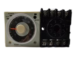
The Larkin H3CR A8 is a versatile timer relay designed for use in industrial and automation applications. This component provides precise control over electrical circuits by offering adjustable timing ranges and multiple timing modes. Its robust design and flexibility make it suitable for a wide range of applications, including motor control, lighting systems, and process automation.

Explore Projects Built with TIMER LARKIN H3CR A8

Use Cirkit Designer to design, explore, and prototype these projects online. Some projects support real-time simulation. Click "Open Project" to start designing instantly!
Light-Activated 555 Timer LED Flasher Circuit
Image of LIC: A project utilizing TIMER LARKIN H3CR A8 in a practical application
This circuit appears to be a light-sensitive timer using a 555 Timer IC configured in astable mode. The photocell (LDR) and resistor form a voltage divider that influences the 555 Timer's trigger (Trig) and threshold (Th) inputs, adjusting the timer's oscillation frequency based on the light intensity. The output of the 555 Timer drives an LED, causing it to blink at a rate that varies with light levels.
Cirkit Designer LogoOpen Project in Cirkit Designer
NFC-Enabled Access Control System with Real-Time Clock and OLED Display
Image of doorlock: A project utilizing TIMER LARKIN H3CR A8 in a practical application
This circuit is designed as an access control system with time-tracking capabilities. It uses an NFC/RFID reader for authentication, a real-time clock for time-stamping events, and an OLED display for user interface, all controlled by a T8_S3 microcontroller. A relay module actuates a magnetic lock, and a button switch provides additional user input, with a switching power supply delivering the necessary voltages.
Cirkit Designer LogoOpen Project in Cirkit Designer
NFC-Enabled Access Control System with Time Logging
Image of doorlock: A project utilizing TIMER LARKIN H3CR A8 in a practical application
This circuit is designed for access control with time tracking capabilities. It features an NFC/RFID reader for authentication, an RTC module (DS3231) for real-time clock functionality, and an OLED display for user interaction. A 12V relay controls a magnetic lock, which is activated upon successful NFC/RFID authentication, and a button switch is likely used for manual operation or input. The T8_S3 microcontroller serves as the central processing unit, interfacing with the NFC/RFID reader, RTC, OLED, and relay to manage the access control logic.
Cirkit Designer LogoOpen Project in Cirkit Designer
555 Timer-Based LED Flasher Circuit with Adjustable Flash Rate
Image of frequency generator: A project utilizing TIMER LARKIN H3CR A8 in a practical application
This circuit is a timer/oscillator using a 555 Timer IC, with an LED to visually indicate the timing intervals. It includes a power transformer and rectifier diode for AC power conversion, and a 3.7V battery for DC power, suggesting dual power supply capability.
Cirkit Designer LogoOpen Project in Cirkit Designer

Explore Projects Built with TIMER LARKIN H3CR A8

Use Cirkit Designer to design, explore, and prototype these projects online. Some projects support real-time simulation. Click "Open Project" to start designing instantly!
Image of LIC: A project utilizing TIMER LARKIN H3CR A8 in a practical application
Light-Activated 555 Timer LED Flasher Circuit
This circuit appears to be a light-sensitive timer using a 555 Timer IC configured in astable mode. The photocell (LDR) and resistor form a voltage divider that influences the 555 Timer's trigger (Trig) and threshold (Th) inputs, adjusting the timer's oscillation frequency based on the light intensity. The output of the 555 Timer drives an LED, causing it to blink at a rate that varies with light levels.
Cirkit Designer LogoOpen Project in Cirkit Designer
Image of doorlock: A project utilizing TIMER LARKIN H3CR A8 in a practical application
NFC-Enabled Access Control System with Real-Time Clock and OLED Display
This circuit is designed as an access control system with time-tracking capabilities. It uses an NFC/RFID reader for authentication, a real-time clock for time-stamping events, and an OLED display for user interface, all controlled by a T8_S3 microcontroller. A relay module actuates a magnetic lock, and a button switch provides additional user input, with a switching power supply delivering the necessary voltages.
Cirkit Designer LogoOpen Project in Cirkit Designer
Image of doorlock: A project utilizing TIMER LARKIN H3CR A8 in a practical application
NFC-Enabled Access Control System with Time Logging
This circuit is designed for access control with time tracking capabilities. It features an NFC/RFID reader for authentication, an RTC module (DS3231) for real-time clock functionality, and an OLED display for user interaction. A 12V relay controls a magnetic lock, which is activated upon successful NFC/RFID authentication, and a button switch is likely used for manual operation or input. The T8_S3 microcontroller serves as the central processing unit, interfacing with the NFC/RFID reader, RTC, OLED, and relay to manage the access control logic.
Cirkit Designer LogoOpen Project in Cirkit Designer
Image of frequency generator: A project utilizing TIMER LARKIN H3CR A8 in a practical application
555 Timer-Based LED Flasher Circuit with Adjustable Flash Rate
This circuit is a timer/oscillator using a 555 Timer IC, with an LED to visually indicate the timing intervals. It includes a power transformer and rectifier diode for AC power conversion, and a 3.7V battery for DC power, suggesting dual power supply capability.
Cirkit Designer LogoOpen Project in Cirkit Designer

Common Applications

  • Industrial automation systems
  • Conveyor belt timing and control
  • Sequential control in manufacturing processes
  • HVAC systems for timed operations
  • Lighting control in commercial and industrial settings

Technical Specifications

Key Technical Details

Parameter Specification
Manufacturer Larkin
Part ID H3CR A8
Power Supply Voltage 100-240V AC or 24-48V DC
Timing Ranges 0.05 seconds to 300 hours (adjustable)
Timing Modes ON-delay, OFF-delay, Interval, One-shot
Contact Configuration DPDT (Double Pole Double Throw)
Contact Rating 5A at 250V AC / 30V DC
Operating Temperature -10°C to +55°C
Mounting Style DIN rail or panel mount
Dimensions 48mm x 48mm x 90mm

Pin Configuration and Descriptions

The Larkin H3CR A8 features an 8-pin configuration. Below is the pinout description:

Pin Number Name Description
1 A1 Power supply input (AC/DC positive terminal)
2 A2 Power supply input (AC/DC negative terminal)
3 15 (COM1) Common terminal for relay 1
4 16 (NO1) Normally open contact for relay 1
5 18 (NC1) Normally closed contact for relay 1
6 25 (COM2) Common terminal for relay 2
7 26 (NO2) Normally open contact for relay 2
8 28 (NC2) Normally closed contact for relay 2

Usage Instructions

How to Use the Larkin H3CR A8 in a Circuit

  1. Power Supply Connection: Connect the power supply to pins A1 and A2. Ensure the voltage matches the specified range (100-240V AC or 24-48V DC).
  2. Load Connection: Connect the load to the relay contacts (pins 15, 16, 18 for relay 1 and pins 25, 26, 28 for relay 2). Use the normally open (NO) or normally closed (NC) contacts based on your application.
  3. Set Timing Range: Use the rotary switches on the front panel to select the desired timing range and mode.
  4. Adjust Timing: Fine-tune the timing using the adjustable knob.
  5. Operation: Once powered, the timer will operate based on the selected mode and timing settings.

Important Considerations

  • Ensure the power supply voltage is within the specified range to avoid damage.
  • Use appropriate wiring and connectors to handle the rated current and voltage.
  • Avoid exposing the timer to extreme temperatures or moisture.
  • For safety, disconnect the power supply before making any wiring changes.

Example: Using the H3CR A8 with an Arduino UNO

The Larkin H3CR A8 can be used with an Arduino UNO to control timing operations. Below is an example of how to interface the timer with an Arduino:

/*
  Example: Controlling the Larkin H3CR A8 Timer with Arduino UNO
  This code demonstrates how to use a digital output pin to trigger the timer.
  Ensure proper wiring between the Arduino and the timer relay.
*/

const int timerTriggerPin = 7; // Arduino pin connected to the timer relay input

void setup() {
  pinMode(timerTriggerPin, OUTPUT); // Set the pin as an output
}

void loop() {
  digitalWrite(timerTriggerPin, HIGH); // Activate the timer relay
  delay(5000); // Keep the relay active for 5 seconds
  digitalWrite(timerTriggerPin, LOW);  // Deactivate the timer relay
  delay(5000); // Wait for 5 seconds before repeating
}

Note: Use an optocoupler or transistor circuit to interface the Arduino with the timer relay if the relay requires higher voltage or current than the Arduino can provide.

Troubleshooting and FAQs

Common Issues and Solutions

Issue Possible Cause Solution
Timer does not power on Incorrect power supply voltage Verify and correct the power supply voltage.
Relay does not activate Faulty wiring or incorrect connections Check and ensure proper wiring of relay contacts.
Timing is inaccurate Incorrect timing range or knob setting Recheck and adjust the timing range and knob.
Timer overheats Exceeding rated current or voltage Ensure the load does not exceed the rated specifications.

FAQs

  1. Can the H3CR A8 operate on both AC and DC power?

    • Yes, it supports both 100-240V AC and 24-48V DC power supplies.
  2. What is the maximum load current for the relay contacts?

    • The relay contacts can handle up to 5A at 250V AC or 30V DC.
  3. Can I use the H3CR A8 for delayed motor start applications?

    • Yes, the ON-delay mode is ideal for delayed motor start applications.
  4. How do I reset the timer?

    • Disconnect the power supply to reset the timer. Reapply power to restart the operation.

By following this documentation, users can effectively integrate the Larkin H3CR A8 timer into their projects and troubleshoot common issues with ease.