Cirkit Designer Logo
Cirkit Designer
Your all-in-one circuit design IDE
Home / 
Component Documentation

How to Use MCP 4735: Examples, Pinouts, and Specs

Image of MCP 4735
Cirkit Designer LogoDesign with MCP 4735 in Cirkit Designer

Introduction

The MCP4735 is a low-power, single-channel digital-to-analog converter (DAC) manufactured by Arduino. It is designed to convert digital signals into precise analog voltage outputs, making it an essential component in applications requiring fine voltage control. With a 10-bit resolution and an I2C interface, the MCP4735 is ideal for use in audio systems, sensor interfacing, and other applications where accurate analog signal generation is required.

Explore Projects Built with MCP 4735

Use Cirkit Designer to design, explore, and prototype these projects online. Some projects support real-time simulation. Click "Open Project" to start designing instantly!
STM32 and ESP32 CAN Bus Communication System with MCP2515
Image of CAR HACKING: A project utilizing MCP 4735 in a practical application
This circuit integrates multiple microcontrollers (STM32F103C8T6, ESP32, and Raspberry Pi Pico W) with MCP2515 CAN controllers to facilitate CAN bus communication. The microcontrollers are connected to the MCP2515 modules via SPI interfaces, and the circuit includes USB-to-serial converters for programming and debugging purposes.
Cirkit Designer LogoOpen Project in Cirkit Designer
Wi-Fi Controlled Relay Module with ESP8266 and MCP23017
Image of smart home: A project utilizing MCP 4735 in a practical application
This circuit is a WiFi-enabled relay control system using an ESP8266-01 module and an MCP23017 I/O expander. The ESP8266 communicates with the MCP23017 via I2C to control an 8-channel relay module based on the state of 8 rocker switches, allowing for remote and manual control of connected devices.
Cirkit Designer LogoOpen Project in Cirkit Designer
I2C-Controlled Relay Switching with ESP32 and MCP23017 for Home Automation
Image of Vloerverwarming: A project utilizing MCP 4735 in a practical application
This circuit appears to be a control system utilizing two MCP23017 I/O expanders interfaced with an Olimex ESP32-EVB microcontroller via I2C communication, as indicated by the SDA and SCL connections with pull-up resistors. The MCP23017 expanders control an 8-channel relay module, allowing the microcontroller to switch various loads, potentially for home automation or industrial control. Additionally, there is an Adafruit ADS1115 16-bit ADC for analog signal measurement, and several heating actuators and a thermostat are connected, suggesting temperature control functionality.
Cirkit Designer LogoOpen Project in Cirkit Designer
ESP32 and MCP2515 CAN Bus Interface with Potentiometer Control
Image of EngineNodeWiringDiagram: A project utilizing MCP 4735 in a practical application
This circuit features an ESP32 microcontroller interfaced with an MCP2515 CAN controller and a potentiometer. The ESP32 reads the analog output from the potentiometer and communicates with the MCP2515 via SPI to potentially transmit or receive CAN messages.
Cirkit Designer LogoOpen Project in Cirkit Designer

Explore Projects Built with MCP 4735

Use Cirkit Designer to design, explore, and prototype these projects online. Some projects support real-time simulation. Click "Open Project" to start designing instantly!
Image of CAR HACKING: A project utilizing MCP 4735 in a practical application
STM32 and ESP32 CAN Bus Communication System with MCP2515
This circuit integrates multiple microcontrollers (STM32F103C8T6, ESP32, and Raspberry Pi Pico W) with MCP2515 CAN controllers to facilitate CAN bus communication. The microcontrollers are connected to the MCP2515 modules via SPI interfaces, and the circuit includes USB-to-serial converters for programming and debugging purposes.
Cirkit Designer LogoOpen Project in Cirkit Designer
Image of smart home: A project utilizing MCP 4735 in a practical application
Wi-Fi Controlled Relay Module with ESP8266 and MCP23017
This circuit is a WiFi-enabled relay control system using an ESP8266-01 module and an MCP23017 I/O expander. The ESP8266 communicates with the MCP23017 via I2C to control an 8-channel relay module based on the state of 8 rocker switches, allowing for remote and manual control of connected devices.
Cirkit Designer LogoOpen Project in Cirkit Designer
Image of Vloerverwarming: A project utilizing MCP 4735 in a practical application
I2C-Controlled Relay Switching with ESP32 and MCP23017 for Home Automation
This circuit appears to be a control system utilizing two MCP23017 I/O expanders interfaced with an Olimex ESP32-EVB microcontroller via I2C communication, as indicated by the SDA and SCL connections with pull-up resistors. The MCP23017 expanders control an 8-channel relay module, allowing the microcontroller to switch various loads, potentially for home automation or industrial control. Additionally, there is an Adafruit ADS1115 16-bit ADC for analog signal measurement, and several heating actuators and a thermostat are connected, suggesting temperature control functionality.
Cirkit Designer LogoOpen Project in Cirkit Designer
Image of EngineNodeWiringDiagram: A project utilizing MCP 4735 in a practical application
ESP32 and MCP2515 CAN Bus Interface with Potentiometer Control
This circuit features an ESP32 microcontroller interfaced with an MCP2515 CAN controller and a potentiometer. The ESP32 reads the analog output from the potentiometer and communicates with the MCP2515 via SPI to potentially transmit or receive CAN messages.
Cirkit Designer LogoOpen Project in Cirkit Designer

Common Applications and Use Cases

  • Audio signal processing
  • Sensor calibration and interfacing
  • Voltage reference generation
  • Precision control systems
  • Industrial automation

Technical Specifications

The MCP4735 is a versatile DAC with the following key technical details:

Parameter Value
Resolution 10-bit
Output Voltage Range 0V to VDD
Supply Voltage (VDD) 2.7V to 5.5V
Interface I2C
Maximum I2C Clock Speed 400 kHz (Fast Mode)
Power Consumption Low-power operation
Operating Temperature -40°C to +125°C
Package 6-pin SOT-23

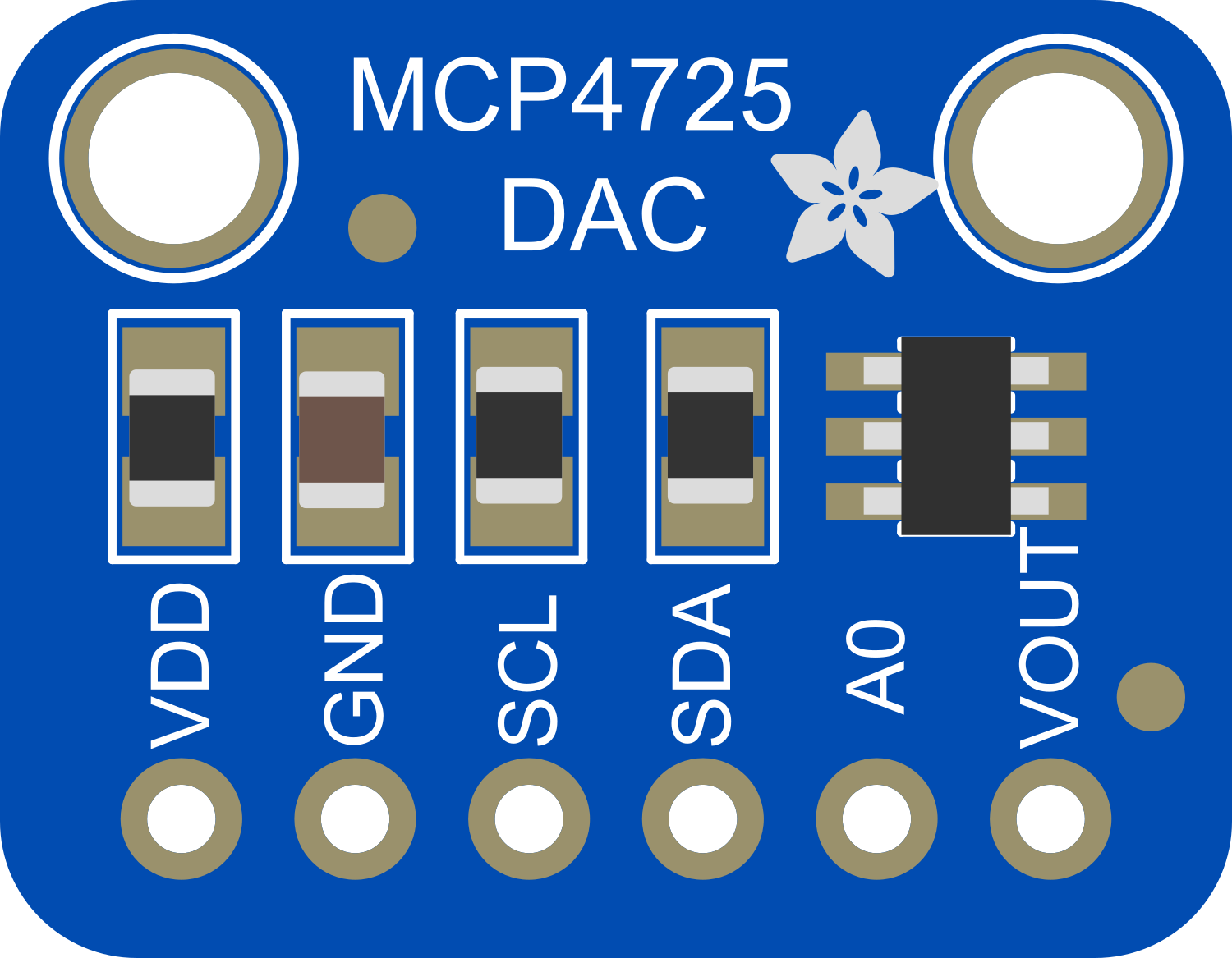
Pin Configuration and Descriptions

The MCP4735 comes in a 6-pin SOT-23 package. Below is the pinout and description:

Pin Number Pin Name Description
1 VDD Positive power supply (2.7V to 5.5V)
2 VOUT Analog voltage output
3 GND Ground
4 SCL I2C clock line
5 SDA I2C data line
6 A0 I2C address selection bit

Usage Instructions

The MCP4735 is straightforward to use in a circuit, thanks to its I2C interface. Below are the steps and considerations for integrating it into your project:

Connecting the MCP4735

  1. Power Supply: Connect the VDD pin to a 2.7V to 5.5V power source and the GND pin to ground.
  2. I2C Interface: Connect the SCL and SDA pins to the corresponding I2C lines of your microcontroller. Use pull-up resistors (typically 4.7kΩ) on both lines if not already present.
  3. Output Voltage: The VOUT pin provides the analog voltage output. Connect this pin to the desired load or circuit.
  4. Address Selection: Use the A0 pin to set the I2C address. Tie it to GND or VDD to select between two possible addresses.

Example: Using MCP4735 with Arduino UNO

Below is an example of how to use the MCP4735 with an Arduino UNO to generate an analog voltage:
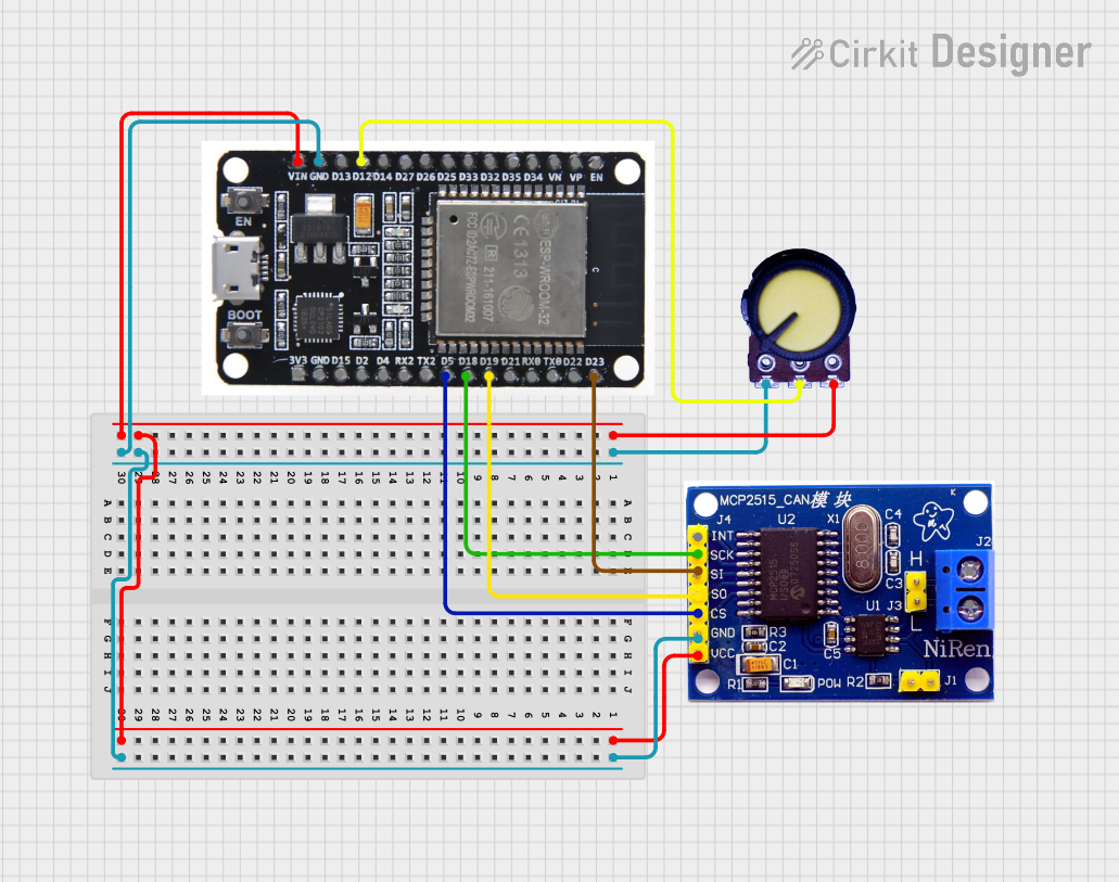
Circuit Diagram

  • Connect MCP4735's VDD to 5V and GND to GND on the Arduino.
  • Connect SCL to A5 and SDA to A4 on the Arduino UNO.
  • Use a pull-up resistor (4.7kΩ) on both SCL and SDA lines.

Arduino Code

#include <Wire.h> // Include the Wire library for I2C communication

#define MCP4735_ADDR 0x60 // Default I2C address of MCP4735 (A0 = GND)

void setup() {
  Wire.begin(); // Initialize I2C communication
  Serial.begin(9600); // Initialize serial communication for debugging
}

void loop() {
  uint16_t value = 512; // 10-bit DAC value (0 to 1023)
  
  // Send the value to the MCP4735
  Wire.beginTransmission(MCP4735_ADDR);
  Wire.write((value >> 8) & 0x0F); // Send the upper 4 bits of the 10-bit value
  Wire.write(value & 0xFF);        // Send the lower 8 bits of the 10-bit value
  Wire.endTransmission();
  
  Serial.println("DAC value sent: " + String(value)); // Debugging output
  delay(1000); // Wait for 1 second before sending the next value
}

Important Considerations

  • I2C Address: Ensure the correct I2C address is used in your code. The default address is 0x60 when A0 is tied to GND.
  • Voltage Range: The output voltage range is from 0V to VDD. Ensure your load is compatible with this range.
  • Pull-up Resistors: Use appropriate pull-up resistors on the I2C lines if not already present in your circuit.

Troubleshooting and FAQs

Common Issues

  1. No Output Voltage:

    • Ensure the MCP4735 is powered correctly (VDD and GND are connected).
    • Verify the I2C connections (SCL and SDA) and check for proper pull-up resistors.
    • Confirm the I2C address in your code matches the hardware configuration.
  2. Incorrect Output Voltage:

    • Check the 10-bit value being sent to the DAC. Ensure it is within the range of 0 to 1023.
    • Verify the power supply voltage (VDD) is stable and within the specified range.
  3. I2C Communication Failure:

    • Ensure the SCL and SDA lines are not shorted or disconnected.
    • Check the pull-up resistors on the I2C lines.
    • Verify the I2C clock speed does not exceed 400 kHz.

FAQs

Q: Can the MCP4735 output negative voltages?
A: No, the MCP4735 can only output voltages in the range of 0V to VDD.

Q: What is the resolution of the MCP4735?
A: The MCP4735 has a 10-bit resolution, meaning it can output 1024 discrete voltage levels.

Q: Can I use the MCP4735 with a 3.3V microcontroller?
A: Yes, the MCP4735 operates with a supply voltage range of 2.7V to 5.5V, making it compatible with 3.3V systems.

Q: How do I change the I2C address of the MCP4735?
A: The I2C address is determined by the state of the A0 pin. Tie A0 to GND or VDD to select between two possible addresses (0x60 or 0x61).