
How to Use Raspberry Pi 5: Examples, Pinouts, and Specs
 Design with Raspberry Pi 5 in Cirkit Designer
Introduction
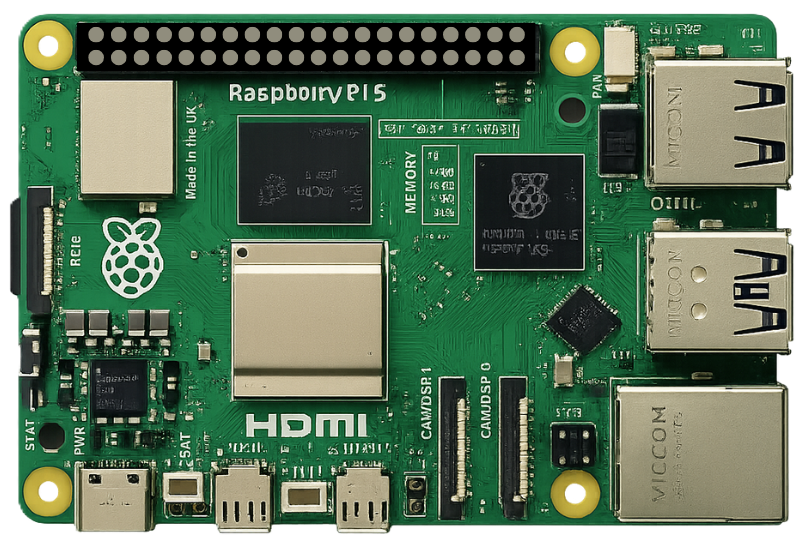
The Raspberry Pi 5 Model B (8GB), manufactured by Raspberry Pi Ltd., is a compact and affordable single-board computer designed for a wide range of applications. It features a powerful ARM-based processor, enhanced graphics capabilities, and multiple connectivity options. The Raspberry Pi 5 is ideal for projects in programming, robotics, IoT, media centers, and more. Its small form factor and versatility make it a popular choice for both hobbyists and professionals.
Explore Projects Built with Raspberry Pi 5
 Open Project in Cirkit Designer
 Open Project in Cirkit Designer
 Open Project in Cirkit Designer
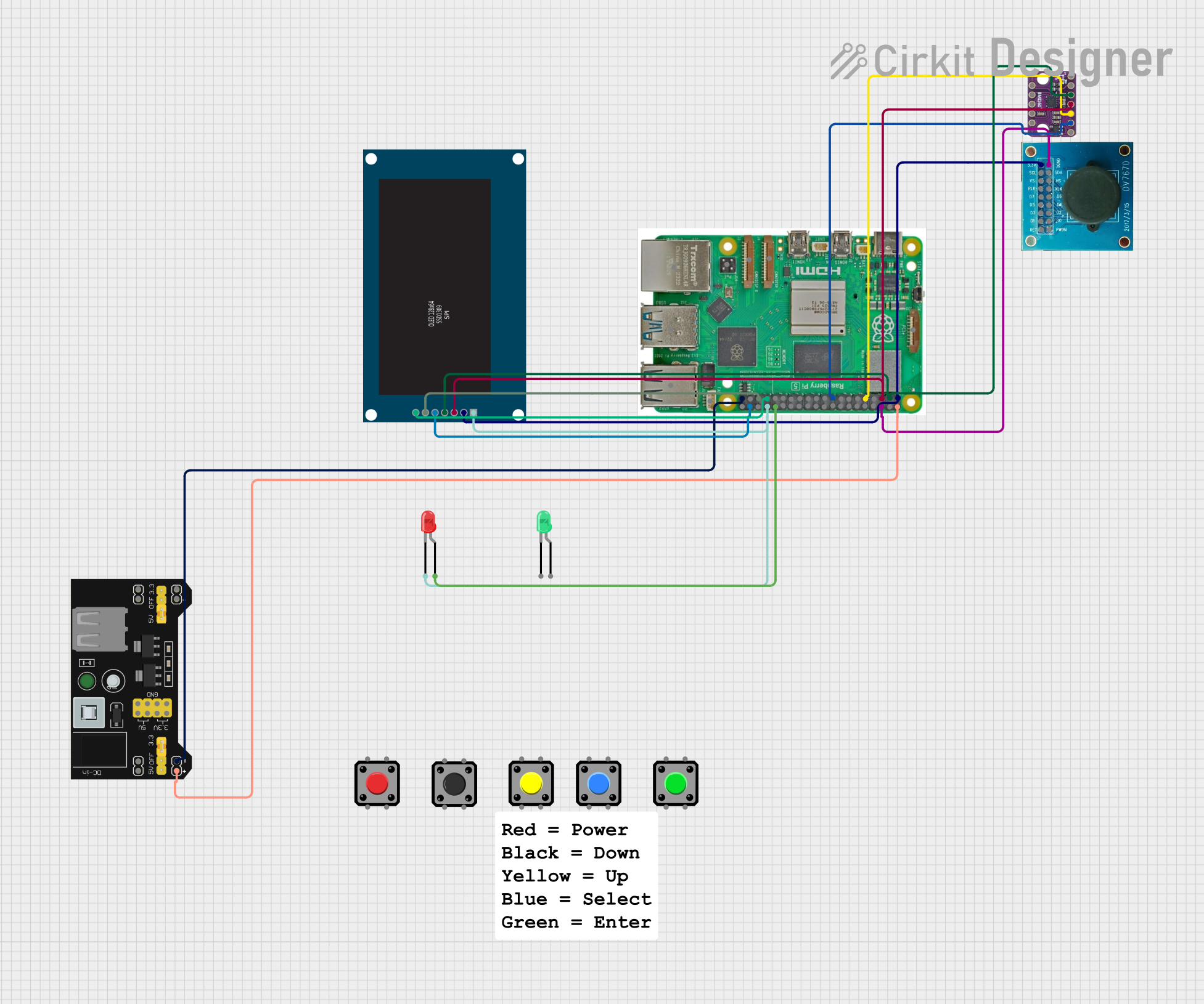 Open Project in Cirkit Designer
Explore Projects Built with Raspberry Pi 5
Open Project in Cirkit DesignerOpen Project in Cirkit DesignerOpen Project in Cirkit DesignerOpen Project in Cirkit DesignerCommon Applications
- Programming and Education: Ideal for learning programming languages like Python, C++, and Java.
- IoT Projects: Acts as a hub for sensors and devices in Internet of Things applications.
- Media Centers: Can be used to build a home theater system with software like Kodi.
- Robotics: Powers robots with its GPIO pins and processing capabilities.
- Edge Computing: Suitable for lightweight AI and machine learning tasks.
- Home Automation: Integrates with smart home devices for automation projects.
Technical Specifications
Key Technical Details
| Specification | Details |
|---|---|
| Processor | Quad-core ARM Cortex-A76, 2.4 GHz |
| RAM | 8GB LPDDR4X |
| GPU | VideoCore VII, supports 4Kp60 H.265 decoding and dual 4K HDMI output |
| Storage | MicroSD card slot, PCIe Gen 2 interface for SSDs |
| Connectivity | Dual-band Wi-Fi 6, Bluetooth 5.0, Gigabit Ethernet |
| USB Ports | 2 × USB 3.0, 2 × USB 2.0 |
| GPIO Pins | 40-pin header, 3.3V logic level |
| Power Supply | USB-C, 5V/5A |
| Dimensions | 85.6mm × 56.5mm × 18mm |
| Operating System | Raspberry Pi OS (Linux-based), supports other OS like Ubuntu and Windows IoT |
Pin Configuration and Descriptions
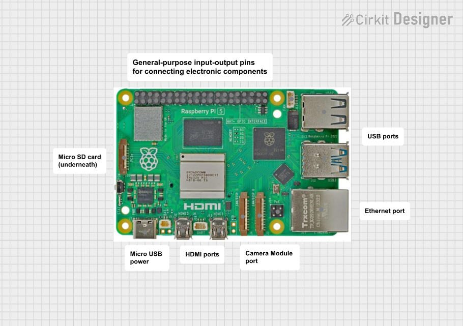
The Raspberry Pi 5 features a 40-pin GPIO header for interfacing with external devices. Below is the pinout:
| Pin Number | Pin Name | Description |
|---|---|---|
| 1 | 3.3V Power | 3.3V power supply |
| 2 | 5V Power | 5V power supply |
| 3 | GPIO2 (SDA1) | I2C Data |
| 4 | 5V Power | 5V power supply |
| 5 | GPIO3 (SCL1) | I2C Clock |
| 6 | Ground | Ground |
| 7 | GPIO4 | General-purpose I/O |
| 8 | GPIO14 (TXD) | UART Transmit |
| 9 | Ground | Ground |
| 10 | GPIO15 (RXD) | UART Receive |
| ... | ... | ... |
| 39 | Ground | Ground |
| 40 | GPIO21 | General-purpose I/O |
For the full GPIO pinout, refer to the official Raspberry Pi documentation.
Usage Instructions
How to Use the Raspberry Pi 5 in a Circuit
- Powering the Raspberry Pi: Use a 5V/5A USB-C power adapter to power the board.
- Connecting Peripherals: Attach a monitor via HDMI, a keyboard and mouse via USB, and a microSD card with the operating system installed.
- GPIO Usage: Connect external devices like LEDs, sensors, or motors to the GPIO pins. Use appropriate resistors and circuits to avoid overloading the pins.
- Networking: Connect to the internet via Wi-Fi 6 or Ethernet for remote access and updates.
Important Considerations
- Heat Management: The Raspberry Pi 5 can generate significant heat under load. Use a heatsink or fan for cooling.
- Power Supply: Ensure the power supply provides sufficient current (5A) to avoid instability.
- Static Protection: Handle the board carefully to avoid damage from static electricity.
- Software Updates: Regularly update the operating system and firmware for optimal performance and security.
Example: Blinking an LED with GPIO
Below is an example of controlling an LED connected to GPIO pin 17 using Python:
Import the GPIO library and time module
import RPi.GPIO as GPIO import time
Set up GPIO mode and pin
GPIO.setmode(GPIO.BCM) # Use Broadcom pin numbering GPIO.setup(17, GPIO.OUT) # Set GPIO 17 as an output pin
try: while True: GPIO.output(17, GPIO.HIGH) # Turn the LED on time.sleep(1) # Wait for 1 second GPIO.output(17, GPIO.LOW) # Turn the LED off time.sleep(1) # Wait for 1 second except KeyboardInterrupt: # Clean up GPIO settings on exit GPIO.cleanup()
**Circuit Setup**:
- Connect the positive leg of the LED to GPIO pin 17.
- Connect the negative leg of the LED to a 330-ohm resistor, and then to a ground pin.

---
Troubleshooting and FAQs
Common Issues
- No Power or Boot Failure:
- Ensure the power supply provides 5V/5A.
- Check the microSD card for a properly installed operating system.
- Overheating:
- Use a heatsink or fan to manage heat during intensive tasks.
- No Display Output:
- Verify the HDMI cable and monitor compatibility.
- Ensure the correct HDMI port is used (HDMI 0 for primary display).
- GPIO Not Working:
- Check the pin configuration and connections.
- Ensure the GPIO library is installed and configured correctly.
FAQs
Q: Can I use a lower-rated power supply?
A: It is not recommended. A lower-rated power supply may cause instability or unexpected shutdowns.Q: What operating systems are supported?
A: The Raspberry Pi 5 supports Raspberry Pi OS, Ubuntu, and Windows IoT Core, among others.Q: How do I update the firmware?
A: Run the following commands in the terminal:sudo apt update sudo apt full-upgradeQ: Can I connect multiple displays?
A: Yes, the Raspberry Pi 5 supports dual 4K displays via its two HDMI ports.
By following this documentation, users can effectively utilize the Raspberry Pi 5 for a variety of projects and applications.