How to Use ИПР 513-10 main: Examples, Pinouts, and Specs
Introduction
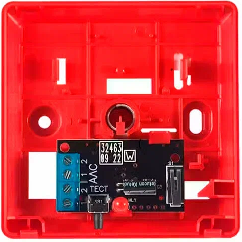
The ИПР 513-10 is an integrated circuit (IC) designed for use in control systems and automation applications. Manufactured by ИПР, this component is known for its reliability, efficiency, and robust performance in processing signals. It is commonly used in industrial automation, signal processing, and control logic systems, where precise and consistent operation is critical.
Explore Projects Built with ИПР 513-10 main


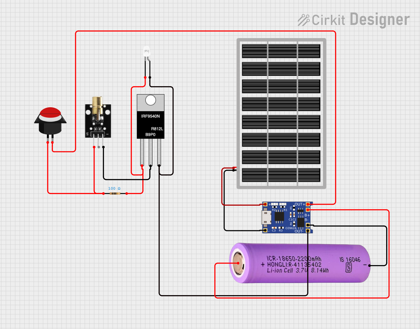
Explore Projects Built with ИПР 513-10 main
Common Applications
- Industrial automation systems
- Signal processing circuits
- Control logic in machinery
- Embedded systems for automation
- Monitoring and feedback systems
Technical Specifications
Key Technical Details
| Parameter | Value |
|---|---|
| Manufacturer | ИПР |
| Part ID | 513-10 |
| Supply Voltage (Vcc) | 5V to 15V |
| Operating Current | 10 mA (typical) |
| Signal Input Voltage | 0V to Vcc |
| Operating Temperature | -40°C to +85°C |
| Package Type | DIP-14 (Dual Inline Package) |
| Signal Processing Speed | 1 MHz |
Pin Configuration and Descriptions
| Pin Number | Pin Name | Description |
|---|---|---|
| 1 | Vcc | Positive power supply input |
| 2 | IN1 | Signal input 1 |
| 3 | IN2 | Signal input 2 |
| 4 | GND | Ground (0V reference) |
| 5 | OUT1 | Signal output 1 |
| 6 | OUT2 | Signal output 2 |
| 7 | CLK | Clock input for synchronization |
| 8 | RESET | Reset input to initialize the IC |
| 9 | ENABLE | Enable input to activate the IC |
| 10 | TEST | Test mode input for diagnostics |
| 11 | NC | No connection |
| 12 | OUT3 | Signal output 3 |
| 13 | IN3 | Signal input 3 |
| 14 | Vcc | Positive power supply input (redundant pin) |
Usage Instructions
How to Use the ИПР 513-10 in a Circuit
- Power Supply: Connect the Vcc pins (1 and 14) to a stable power source within the range of 5V to 15V. Connect the GND pin (4) to the ground of the circuit.
- Signal Inputs: Feed the input signals to the IN1, IN2, and IN3 pins (2, 3, and 13). Ensure the input voltage levels are within the specified range (0V to Vcc).
- Outputs: The processed signals will be available at the OUT1, OUT2, and OUT3 pins (5, 6, and 12). Connect these to the desired load or subsequent circuit stages.
- Clock and Reset: Provide a clock signal to the CLK pin (7) for synchronization, and use the RESET pin (8) to initialize the IC as needed.
- Enable and Test: Use the ENABLE pin (9) to activate the IC. The TEST pin (10) can be used for diagnostic purposes during development or troubleshooting.
Important Considerations and Best Practices
- Decoupling Capacitors: Place a 0.1 µF ceramic capacitor close to the Vcc and GND pins to filter out noise and stabilize the power supply.
- Signal Integrity: Use proper shielding and grounding techniques to minimize noise in the input signals.
- Clock Signal: Ensure the clock signal is clean and within the specified frequency range to avoid erratic behavior.
- Thermal Management: Operate the IC within the specified temperature range (-40°C to +85°C) to prevent overheating and ensure long-term reliability.
Example: Connecting to an Arduino UNO
The ИПР 513-10 can be interfaced with an Arduino UNO for control and signal processing. Below is an example code snippet to demonstrate basic usage:
// Example: Interfacing ИПР 513-10 with Arduino UNO
// This code sends a clock signal and reads outputs from the ИПР 513-10

#define CLK_PIN 7    // Arduino pin connected to ИПР CLK pin
#define RESET_PIN 8  // Arduino pin connected to ИПР RESET pin
#define ENABLE_PIN 9 // Arduino pin connected to ИПР ENABLE pin
#define OUT1_PIN 2   // Arduino pin connected to ИПР OUT1 pin
#define OUT2_PIN 3   // Arduino pin connected to ИПР OUT2 pin

void setup() {
  pinMode(CLK_PIN, OUTPUT);    // Set CLK pin as output
  pinMode(RESET_PIN, OUTPUT);  // Set RESET pin as output
  pinMode(ENABLE_PIN, OUTPUT); // Set ENABLE pin as output
  pinMode(OUT1_PIN, INPUT);    // Set OUT1 pin as input
  pinMode(OUT2_PIN, INPUT);    // Set OUT2 pin as input

  digitalWrite(RESET_PIN, HIGH); // Reset the ИПР 513-10
  delay(10);                     // Wait for reset to complete
  digitalWrite(RESET_PIN, LOW);  // Release reset
  digitalWrite(ENABLE_PIN, HIGH); // Enable the ИПР 513-10
}

void loop() {
  // Generate a clock signal
  digitalWrite(CLK_PIN, HIGH);
  delayMicroseconds(500); // 1 kHz clock frequency
  digitalWrite(CLK_PIN, LOW);
  delayMicroseconds(500);

  // Read outputs from ИПР 513-10
  int out1 = digitalRead(OUT1_PIN);
  int out2 = digitalRead(OUT2_PIN);

  // Print the output values to the serial monitor
  Serial.begin(9600);
  Serial.print("OUT1: ");
  Serial.println(out1);
  Serial.print("OUT2: ");
  Serial.println(out2);

  delay(100); // Small delay for stability
}
Troubleshooting and FAQs
Common Issues and Solutions
No Output Signal:
- Ensure the ENABLE pin is set to HIGH to activate the IC.
- Verify that the input signals are within the specified voltage range.
- Check the power supply connections and ensure Vcc and GND are properly connected.
Erratic Behavior:
- Verify the clock signal is clean and within the specified frequency range.
- Check for noise or interference in the input signals and use proper shielding if necessary.
- Ensure the IC is operating within the specified temperature range.
Overheating:
- Confirm that the supply voltage does not exceed the maximum rating.
- Ensure adequate ventilation or cooling in the circuit design.
FAQs
Q: Can the ИПР 513-10 operate at 3.3V?
A: No, the minimum supply voltage for the ИПР 513-10 is 5V. Operating below this voltage may result in malfunction or damage.
Q: What is the purpose of the TEST pin?
A: The TEST pin is used for diagnostic purposes during development or troubleshooting. It is not typically required for normal operation.
Q: Can I leave unused input pins floating?
A: No, unused input pins should be tied to GND or Vcc through a pull-down or pull-up resistor to prevent erratic behavior.