How to Use 4A Active Equalizer Balancer: Examples, Pinouts, and Specs
Introduction
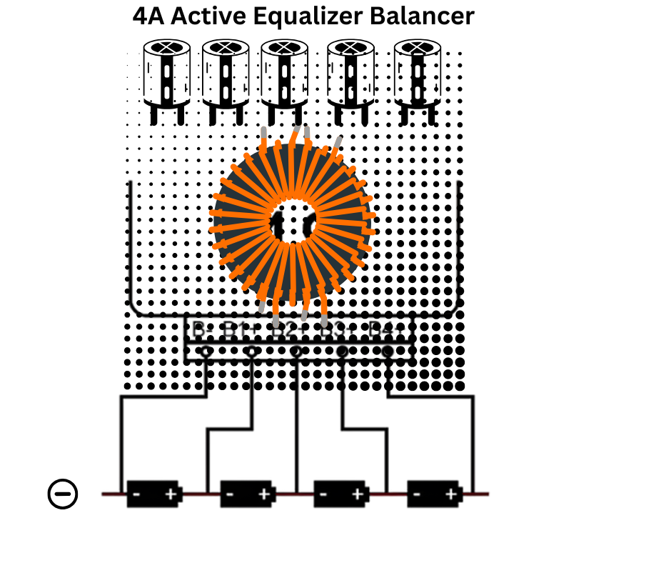
The 4A Active Equalizer Balancer (Manufacturer: Orland, Part ID: Orlando Sudoy) is a high-performance device designed to actively adjust and balance audio frequencies in sound systems. By equalizing audio signals, it enhances sound quality and clarity, making it an essential component in professional audio setups, home theaters, and automotive sound systems.
Explore Projects Built with 4A Active Equalizer Balancer
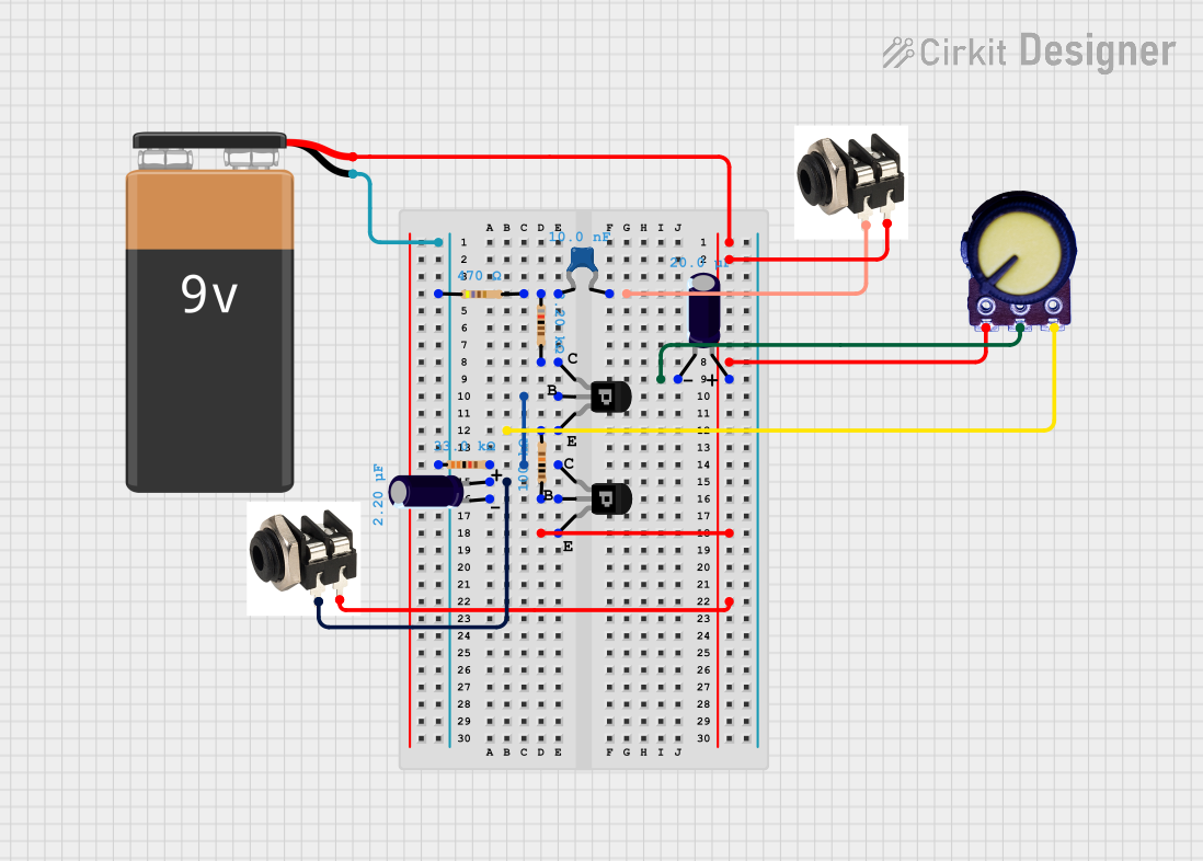


Explore Projects Built with 4A Active Equalizer Balancer
Common Applications and Use Cases
- Professional Audio Systems: Used in concert halls, recording studios, and live sound setups to fine-tune audio output.
- Home Theater Systems: Enhances the listening experience by balancing bass, midrange, and treble frequencies.
- Automotive Audio Systems: Improves sound clarity and quality in car audio setups.
- Public Address Systems: Ensures clear and balanced audio for announcements and presentations.
Technical Specifications
The following table outlines the key technical details of the 4A Active Equalizer Balancer:
| Parameter | Value |
|---|---|
| Operating Voltage | 12V DC |
| Current Rating | 4A |
| Frequency Range | 20 Hz to 20 kHz |
| Signal-to-Noise Ratio | ≥ 90 dB |
| Total Harmonic Distortion (THD) | ≤ 0.01% |
| Input Impedance | 10 kΩ |
| Output Impedance | 600 Ω |
| Dimensions | 100mm x 50mm x 25mm |
| Weight | 150g |
Pin Configuration and Descriptions
The 4A Active Equalizer Balancer features the following pin configuration:
| Pin Number | Pin Name | Description |
|---|---|---|
| 1 | VCC | Power supply input (12V DC) |
| 2 | GND | Ground connection |
| 3 | Audio In L | Left channel audio input |
| 4 | Audio In R | Right channel audio input |
| 5 | Audio Out L | Left channel audio output |
| 6 | Audio Out R | Right channel audio output |
| 7 | EQ Control | Equalizer control input (adjustable via potentiometer or MCU) |
Usage Instructions
How to Use the Component in a Circuit
- Power Supply: Connect the VCC pin to a stable 12V DC power source and the GND pin to the ground.
- Audio Input: Feed the left and right audio signals into the
Audio In LandAudio In Rpins, respectively. - Audio Output: Connect the
Audio Out LandAudio Out Rpins to the input of an amplifier or speaker system. - Equalizer Control: Use the
EQ Controlpin to adjust the frequency balance. This can be done manually using a potentiometer or programmatically using a microcontroller.
Important Considerations and Best Practices
- Power Supply: Ensure the power supply is stable and within the specified voltage range to avoid damage to the component.
- Signal Integrity: Use shielded cables for audio input and output connections to minimize noise and interference.
- Heat Dissipation: If the device operates for extended periods, ensure proper ventilation to prevent overheating.
- Microcontroller Integration: When connecting to an Arduino UNO or similar microcontroller, use the
EQ Controlpin to dynamically adjust the equalizer settings.
Example Arduino Code for EQ Control
The following code demonstrates how to adjust the equalizer settings using an Arduino UNO:
// Define the EQ Control pin
const int eqControlPin = 9; // Connect EQ Control pin to Arduino pin 9

void setup() {
  // Initialize the EQ Control pin as an output
  pinMode(eqControlPin, OUTPUT);
}

void loop() {
  // Example: Gradually increase and decrease the EQ control signal
  for (int i = 0; i <= 255; i++) {
    analogWrite(eqControlPin, i); // Send PWM signal to adjust EQ
    delay(10); // Wait for 10ms
  }
  for (int i = 255; i >= 0; i--) {
    analogWrite(eqControlPin, i); // Reverse the adjustment
    delay(10); // Wait for 10ms
  }
}
Notes:
- The
EQ Controlpin accepts a PWM signal (0-255) to adjust the equalizer settings. - Use a low-pass filter if precise analog control is required.
Troubleshooting and FAQs
Common Issues and Solutions
No Audio Output:
- Cause: Incorrect wiring or loose connections.
- Solution: Verify all connections, especially the audio input and output pins.
Distorted Sound:
- Cause: Overdriven input signal or incorrect power supply voltage.
- Solution: Ensure the input signal is within the acceptable range and the power supply is stable at 12V DC.
Excessive Noise:
- Cause: Poor grounding or unshielded cables.
- Solution: Use shielded cables and ensure a proper ground connection.
Overheating:
- Cause: Prolonged operation without adequate ventilation.
- Solution: Ensure proper airflow around the device or use a heatsink if necessary.
FAQs
Q1: Can the 4A Active Equalizer Balancer be used with a 24V power supply?
A1: No, the device is designed to operate at 12V DC. Using a higher voltage may damage the component.
Q2: How do I adjust the equalizer settings manually?
A2: Connect a potentiometer to the EQ Control pin and adjust it to vary the frequency balance.
Q3: Is the device compatible with digital audio signals?
A3: No, the 4A Active Equalizer Balancer is designed for analog audio signals only.
Q4: Can I use this device in a mono audio system?
A4: Yes, connect the mono audio signal to both Audio In L and Audio In R pins for balanced output.
This concludes the documentation for the 4A Active Equalizer Balancer. For further assistance, refer to the manufacturer's datasheet or contact Orland support.