How to Use ESP32-S3-DevKitC-1-N8R2 small: Examples, Pinouts, and Specs
Introduction
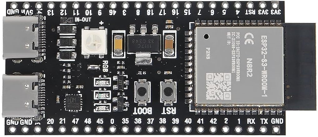
The ESP32-S3-DevKitC-1-N8R2 Small is a compact development board manufactured by XIITIA (Part ID: B0D3C2KJVD). It is built around the ESP32-S3 microcontroller, which features dual-core Xtensa LX7 processors, integrated Wi-Fi (802.11 b/g/n), and Bluetooth 5.0 LE capabilities. This board is designed for IoT applications, rapid prototyping, and edge computing tasks, offering a balance of performance, connectivity, and power efficiency.
Explore Projects Built with ESP32-S3-DevKitC-1-N8R2 small


Explore Projects Built with ESP32-S3-DevKitC-1-N8R2 small
Common Applications
- IoT devices and smart home systems
- Wearable technology
- Wireless sensor networks
- Industrial automation
- Machine learning at the edge
- Prototyping for Wi-Fi and Bluetooth-enabled devices
Technical Specifications
The following table outlines the key technical details of the ESP32-S3-DevKitC-1-N8R2 Small:
| Specification | Details |
|---|---|
| Microcontroller | ESP32-S3 (Xtensa LX7 dual-core, 240 MHz) |
| Flash Memory | 8 MB (N8R2 variant) |
| PSRAM | 2 MB |
| Wireless Connectivity | Wi-Fi 802.11 b/g/n, Bluetooth 5.0 LE |
| Operating Voltage | 3.3V |
| Input Voltage Range | 5V (via USB Type-C) |
| GPIO Pins | 21 (multipurpose, including ADC, DAC, I2C, SPI, UART, PWM) |
| USB Interface | USB Type-C (supports programming and power supply) |
| Dimensions | 48.3 mm x 25.4 mm |
| Operating Temperature | -40°C to +85°C |
| Power Consumption | Ultra-low power modes supported |
Pin Configuration and Descriptions
The ESP32-S3-DevKitC-1-N8R2 Small features a 2x10 pin header layout. Below is the pinout description:
| Pin | Name | Function |
|---|---|---|
| 1 | 3V3 | 3.3V power output |
| 2 | GND | Ground |
| 3 | IO0 | GPIO0, used for boot mode selection |
| 4 | IO1 | GPIO1, UART TXD (default) |
| 5 | IO2 | GPIO2, ADC2 channel |
| 6 | IO3 | GPIO3, UART RXD (default) |
| 7 | IO4 | GPIO4, PWM output |
| 8 | IO5 | GPIO5, SPI SCK |
| 9 | IO6 | GPIO6, SPI MISO |
| 10 | IO7 | GPIO7, SPI MOSI |
| 11 | IO8 | GPIO8, I2C SDA |
| 12 | IO9 | GPIO9, I2C SCL |
| 13 | IO10 | GPIO10, ADC1 channel |
| 14 | IO11 | GPIO11, PWM output |
| 15 | IO12 | GPIO12, UART CTS |
| 16 | IO13 | GPIO13, UART RTS |
| 17 | IO14 | GPIO14, DAC1 |
| 18 | IO15 | GPIO15, DAC2 |
| 19 | EN | Enable pin (active high) |
| 20 | GND | Ground |
Usage Instructions
How to Use the ESP32-S3-DevKitC-1-N8R2 Small in a Circuit
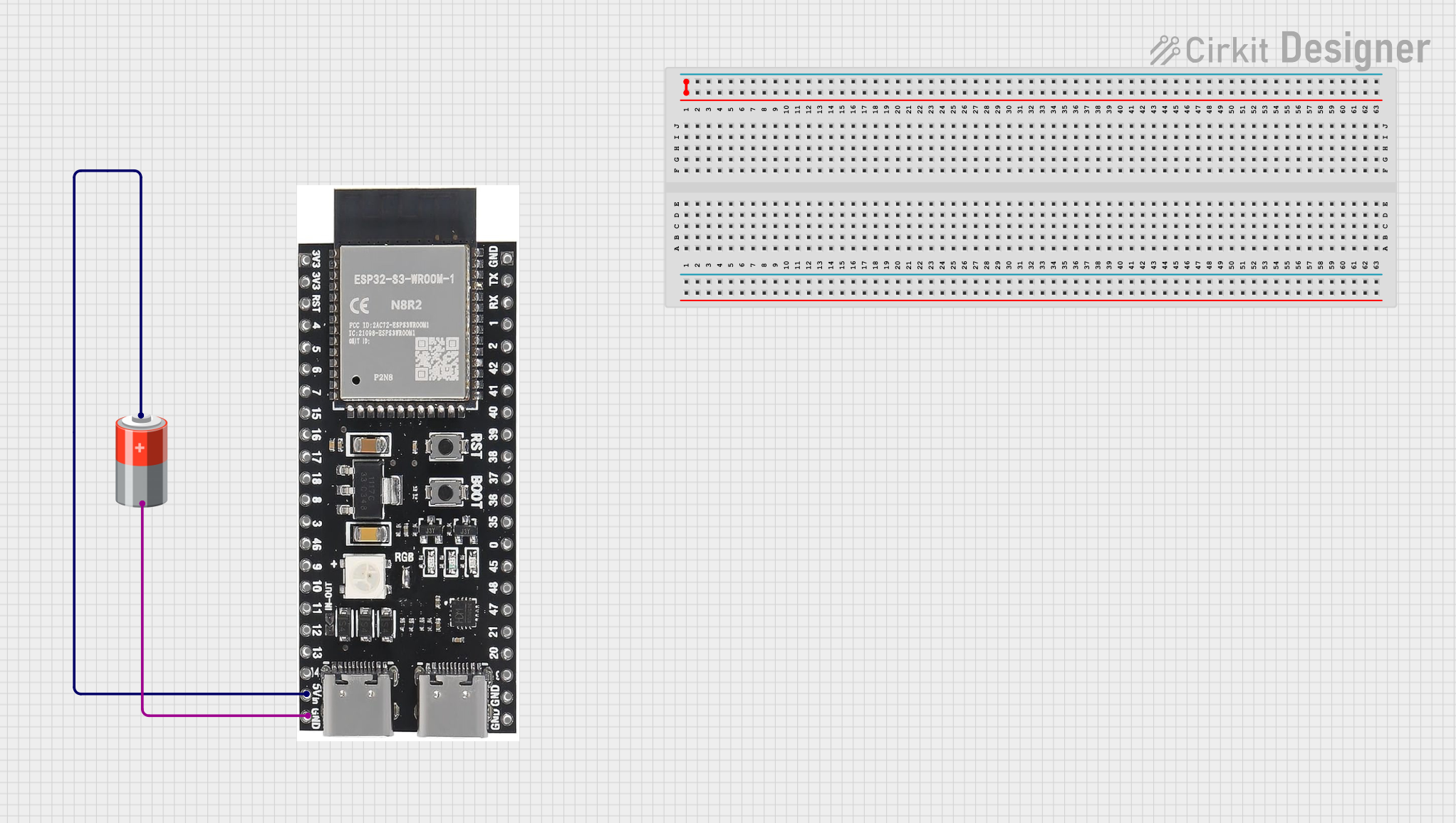
Powering the Board:
- Connect the board to a computer or power source using a USB Type-C cable. The board operates at 3.3V internally but accepts 5V input via USB.
Programming the Board:
- Install the Arduino IDE or ESP-IDF (Espressif IoT Development Framework) on your computer.
- Add the ESP32-S3 board support package to your development environment.
- Select the correct board and port in the IDE settings.
Connecting Peripherals:
- Use the GPIO pins to connect sensors, actuators, or other peripherals. Refer to the pin configuration table for specific pin functions.
Uploading Code:
- Write your program in the IDE and upload it to the board via the USB connection. The onboard bootloader simplifies the process.
Important Considerations and Best Practices
- Voltage Levels: Ensure all connected peripherals operate at 3.3V logic levels to avoid damaging the board.
- Boot Mode: To enter bootloader mode manually, hold the IO0 button while pressing the EN button.
- Power Consumption: Use the ultra-low power modes for battery-powered applications to extend runtime.
- Antenna Placement: Avoid placing metal objects near the onboard antenna to maintain optimal wireless performance.
Example Code for Arduino UNO Integration
The following example demonstrates how to blink an LED connected to GPIO4:
// Define the GPIO pin for the LED
#define LED_PIN 4

void setup() {
  // Set the LED pin as an output
  pinMode(LED_PIN, OUTPUT);
}

void loop() {
  // Turn the LED on
  digitalWrite(LED_PIN, HIGH);
  delay(1000); // Wait for 1 second

  // Turn the LED off
  digitalWrite(LED_PIN, LOW);
  delay(1000); // Wait for 1 second
}
Troubleshooting and FAQs
Common Issues and Solutions
Board Not Detected by Computer:
- Ensure the USB cable is functional and supports data transfer.
- Verify that the correct drivers for the ESP32-S3 are installed on your computer.
Code Upload Fails:
- Check that the correct board and port are selected in the IDE.
- If the issue persists, manually enter bootloader mode by holding IO0 and pressing EN.
Wi-Fi or Bluetooth Not Working:
- Ensure the antenna area is unobstructed.
- Verify that the correct credentials or pairing settings are used in your code.
Overheating:
- Avoid overloading the GPIO pins with excessive current.
- Ensure proper ventilation if the board is used in a confined space.
FAQs
Q: Can I power the board with a battery?
A: Yes, you can use a 3.7V LiPo battery with a suitable voltage regulator to provide 3.3V to the board.
Q: What is the maximum current output of the 3V3 pin?
A: The 3V3 pin can supply up to 500 mA, depending on the input power source.
Q: Does the board support OTA (Over-the-Air) updates?
A: Yes, the ESP32-S3 supports OTA updates, which can be implemented using the ESP-IDF or Arduino libraries.
Q: Can I use this board for machine learning applications?
A: Absolutely! The ESP32-S3 includes hardware acceleration for AI tasks, making it suitable for lightweight machine learning models.
This concludes the documentation for the ESP32-S3-DevKitC-1-N8R2 Small. For further assistance, refer to the official XIITIA resources or community forums.