How to Use AC Dimmer Lamp Module: Examples, Pinouts, and Specs
Introduction
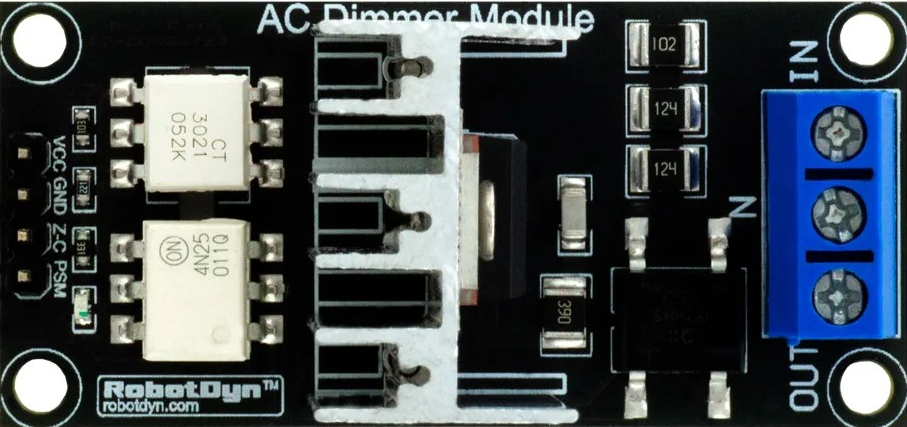
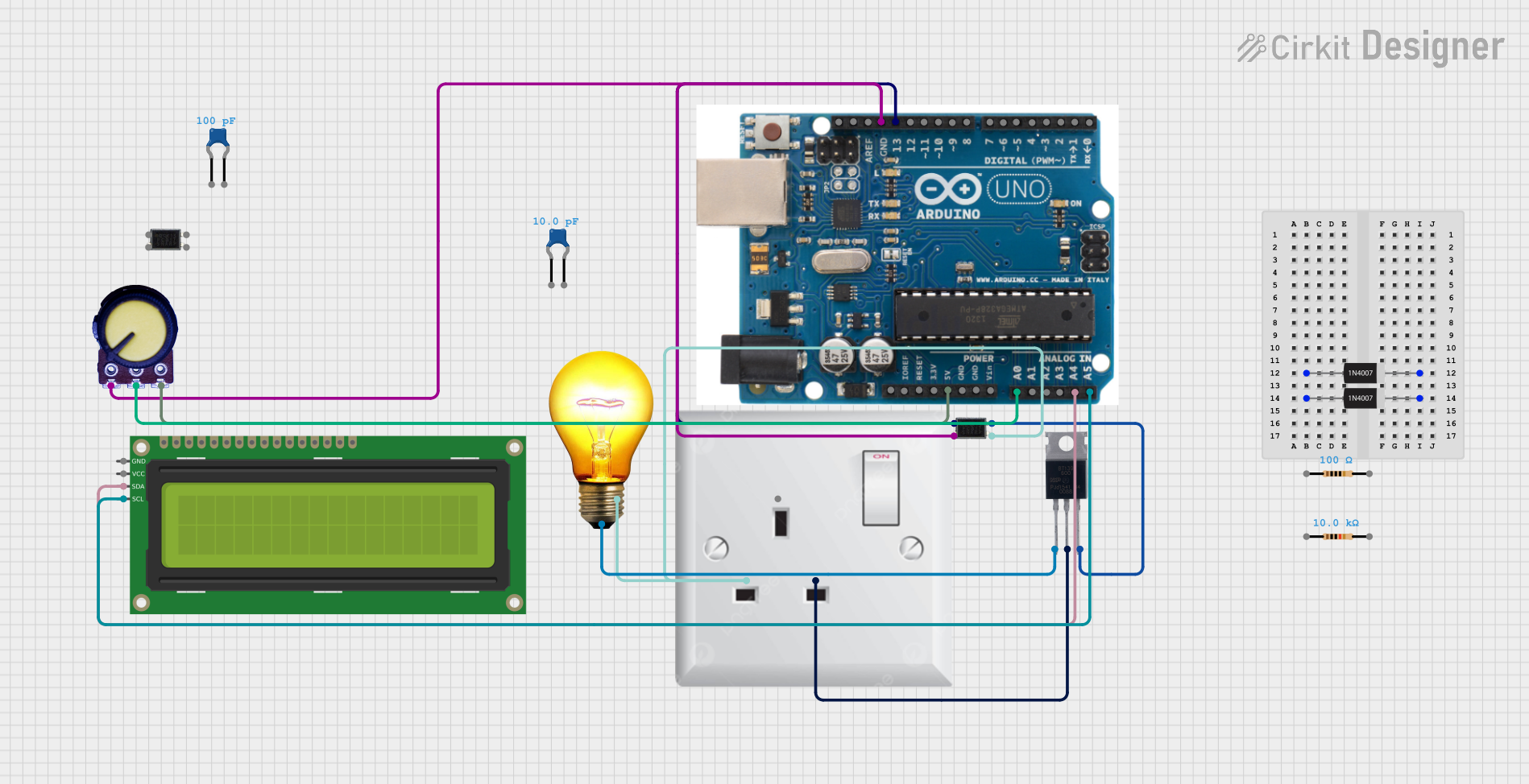
An AC Dimmer Lamp Module is an electronic device designed to adjust the brightness of an incandescent lamp. It works by varying the voltage supplied to the lamp, which in turn dims or brightens the light output. This module is commonly used in residential and commercial lighting systems to create ambient lighting and reduce energy consumption.
Explore Projects Built with AC Dimmer Lamp Module
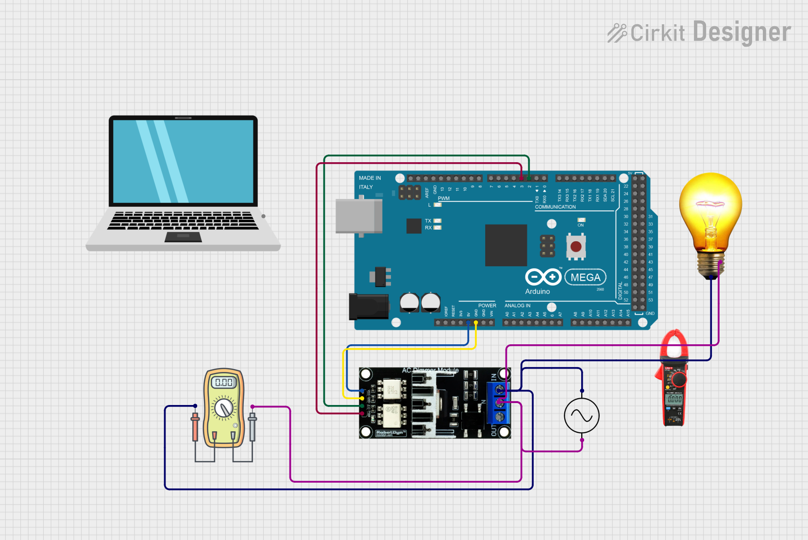
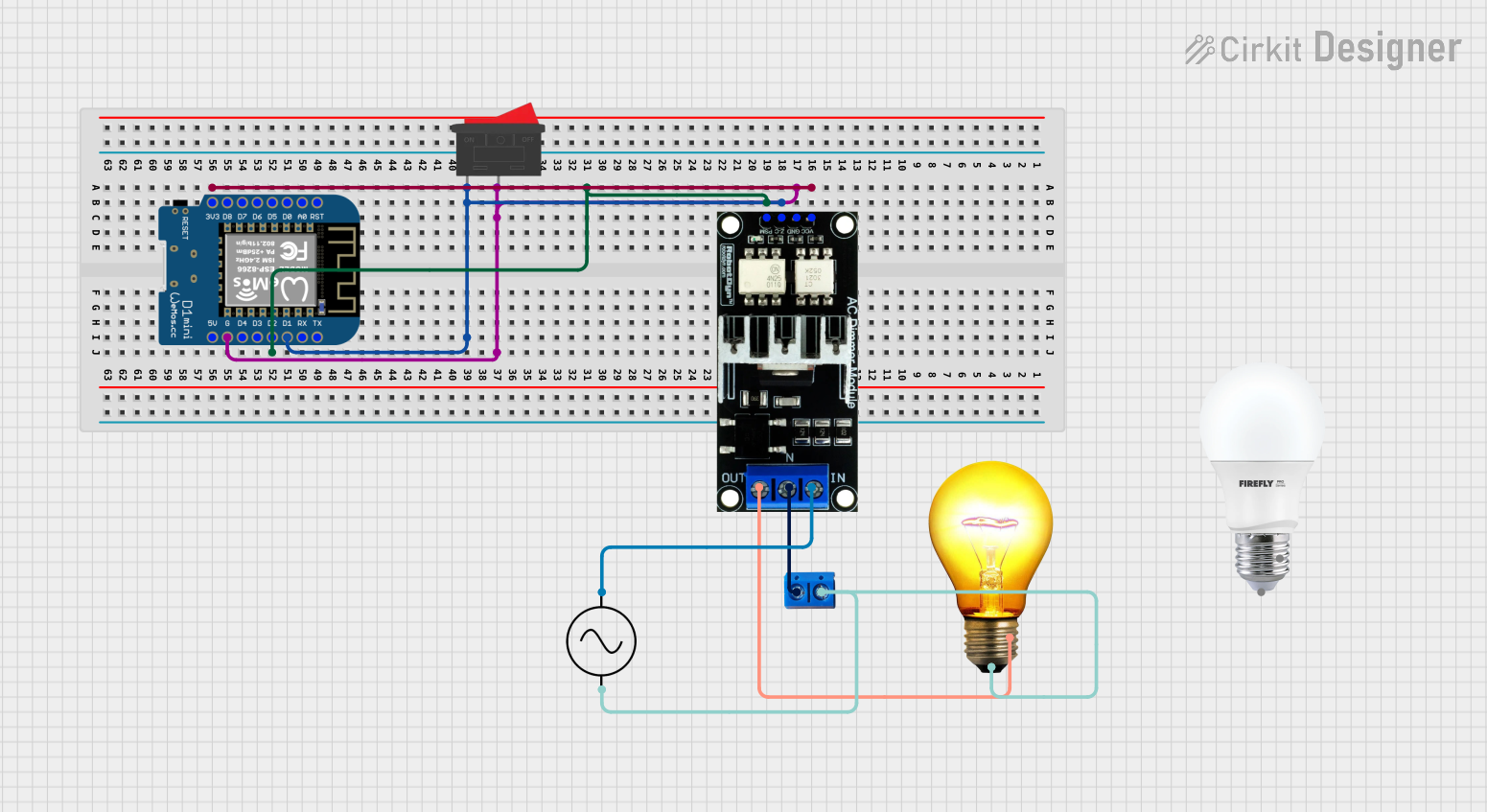
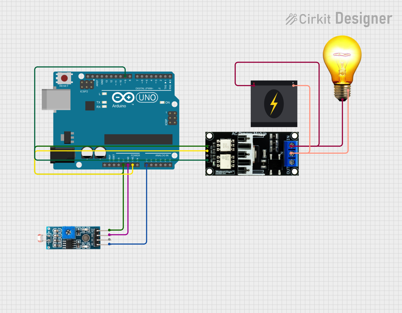
Explore Projects Built with AC Dimmer Lamp Module
Common Applications and Use Cases
- Home lighting systems for mood and ambiance control
- Theatrical lighting to adjust stage lighting intensity
- Restaurant and retail spaces for creating a desired atmosphere
- Smart home systems for energy-saving and automated lighting control
Technical Specifications
Key Technical Details
- Input Voltage: Typically 110V or 220V AC (depending on the region)
- Output Voltage: Variable, up to the input voltage
- Maximum Power Rating: Varies by model (e.g., 250W, 600W, etc.)
- Frequency: 50Hz/60Hz depending on local mains supply
- Control Method: Phase-cut dimming (usually TRIAC-based)
Pin Configuration and Descriptions
| Pin Number | Description | Notes |
|---|---|---|
| 1 | AC Input (Live) | Connect to live wire of AC mains |
| 2 | AC Input (Neutral) | Connect to neutral wire of AC mains |
| 3 | Control Input | Connect to PWM output from microcontroller |
| 4 | Ground (for Control Input) | Connect to microcontroller ground |
Usage Instructions
How to Use the Component in a Circuit
- Connect the AC Mains: Attach the live and neutral wires from the AC mains to the respective input pins on the dimmer module.
- Microcontroller Connection: Connect the control input pin to a PWM-capable pin on the microcontroller and the ground pin to the microcontroller's ground.
- Load Connection: Connect the lamp's live wire to the output of the dimmer module, and its neutral wire directly to the mains neutral.
Important Considerations and Best Practices
- Ensure the module's power rating exceeds the total wattage of the lamps being controlled.
- Use appropriate heat sinks if necessary to dissipate heat generated by the module.
- Always isolate the low voltage control circuit from the high voltage AC side.
- Implement a zero-crossing detection circuit for more precise control and to reduce electrical noise.
Example Code for Arduino UNO
// Example code to control an AC Dimmer Lamp Module with an Arduino UNO

#include <TimerOne.h> // Include TimerOne library for precise timing

// Define the control pin
const int dimmerPin = 9; // Connect to the control input of the dimmer module

// Define the brightness level (0-100%)
int brightness = 50; // Set initial brightness to 50%

// Interrupt service routine to set the dimming level
void setDimming() {
  int dimtime = (75 * brightness); // Calculate dim time based on brightness
  delayMicroseconds(dimtime); // Wait for the appropriate dim time
  digitalWrite(dimmerPin, HIGH); // Turn on the lamp
  delayMicroseconds(10); // Short delay to ensure the TRIAC latches
  digitalWrite(dimmerPin, LOW); // Turn off the lamp
}

void setup() {
  pinMode(dimmerPin, OUTPUT); // Set the dimmer pin as an output
  Timer1.initialize(10000); // Initialize Timer1 to run every 10ms
  Timer1.attachInterrupt(setDimming); // Attach the interrupt service routine
}

void loop() {
  // The main loop can be used to change the brightness over time or in response to sensors or inputs
}
Troubleshooting and FAQs
Common Issues Users Might Face
- Flickering Lights: This may be due to incorrect wiring, insufficient power rating, or a faulty module.
- No Dimming Effect: Ensure the control input is receiving the correct PWM signal and that the module is compatible with the lamp type.
Solutions and Tips for Troubleshooting
- Double-check all connections and ensure they are secure and correct.
- Verify that the microcontroller is generating the correct PWM signal.
- Test the module with a known working lamp to rule out lamp issues.
- Ensure the module's specifications match the requirements of your application.
FAQs
Q: Can I use the AC Dimmer Lamp Module with LED bulbs? A: Most AC dimmer modules are designed for incandescent lamps and may not work correctly with LEDs unless they are specifically labeled as dimmable LEDs.
Q: Is it safe to handle the AC Dimmer Lamp Module while powered? A: No, always turn off the mains power before handling the module to avoid the risk of electric shock.
Q: How can I increase the dimming resolution? A: Use a microcontroller with a higher PWM resolution or implement a zero-crossing detection circuit for finer control over the dimming level.