Cirkit Designer Logo
Cirkit Designer
Your all-in-one circuit design IDE
Home / 
Component Documentation

How to Use Adafruit 8x16 LED Matrix FeatherWing - Yellow-Green: Examples, Pinouts, and Specs

Image of Adafruit 8x16 LED Matrix FeatherWing - Yellow-Green
Cirkit Designer LogoDesign with Adafruit 8x16 LED Matrix FeatherWing - Yellow-Green in Cirkit Designer

Introduction

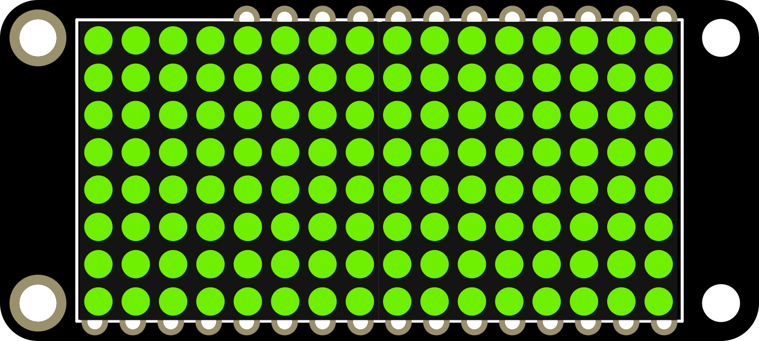
The Adafruit 8x16 LED Matrix FeatherWing in Yellow-Green is a compact and versatile display module designed for use with the Adafruit Feather series of development boards. This LED matrix provides a grid of 8x16 yellow-green LEDs, allowing for the creation of eye-catching displays including scrolling text, animations, and simple graphics. It is an ideal choice for wearable projects, portable instruments, and any application where a small yet readable display is required.

Explore Projects Built with Adafruit 8x16 LED Matrix FeatherWing - Yellow-Green

Use Cirkit Designer to design, explore, and prototype these projects online. Some projects support real-time simulation. Click "Open Project" to start designing instantly!
Arduino UNO Controlled LED Matrix and LCD Interface with Joystick Interaction
Image of Digital Game Circuit: A project utilizing Adafruit 8x16 LED Matrix FeatherWing - Yellow-Green in a practical application
This circuit features an Arduino UNO microcontroller interfaced with an 8x8 LED matrix, an LCD screen, and a KY-023 Dual Axis Joystick Module. The Arduino controls the LED matrix via digital pins D10-D12 and powers the matrix, LCD, and joystick module from its 5V output. The joystick's analog outputs are connected to the Arduino's analog inputs A0 and A1 for position sensing, while the LCD is controlled through digital pins D2-D6 and D13 for display purposes.
Cirkit Designer LogoOpen Project in Cirkit Designer
Arduino-Controlled RGB LED Matrix Display
Image of SMD2121 Led screen: A project utilizing Adafruit 8x16 LED Matrix FeatherWing - Yellow-Green in a practical application
This circuit connects an Arduino UNO R4 WiFi microcontroller to a 64x32 LED matrix display. The Arduino is configured to control the LED matrix, sending color data and control signals to display various colors across the matrix. The embedded code on the Arduino cycles through a range of colors, filling the entire LED matrix with each color in sequence.
Cirkit Designer LogoOpen Project in Cirkit Designer
Arduino UNO Controlled Multi-Matrix LED Display
Image of Test matrix with pixel moving: A project utilizing Adafruit 8x16 LED Matrix FeatherWing - Yellow-Green in a practical application
This circuit consists of an Arduino UNO microcontroller connected to multiple MAX7219 8x8 LED Matrix modules arranged in a daisy-chain configuration. The Arduino controls the LED matrices using a software-implemented SPI communication protocol, with the purpose of displaying complex patterns or animations across the combined matrix display. The provided code handles the initialization and updating of the LED matrices, creating visual effects by manipulating the framebuffer and sending the data to the LED matrices in the correct order.
Cirkit Designer LogoOpen Project in Cirkit Designer
Arduino-Controlled Dual WS2812 RGB LED Matrix Eye Animation Display
Image of eye project: A project utilizing Adafruit 8x16 LED Matrix FeatherWing - Yellow-Green in a practical application
This circuit consists of an Arduino UNO microcontroller connected to two daisy-chained WS2812 RGB LED 8x8 matrices. The Arduino controls the LED matrices to display patterns that simulate a slow blinking human eyes effect. The code for the Arduino is written to create and cycle through different eye patterns, varying from open to half-closed to closed, to achieve the blinking effect.
Cirkit Designer LogoOpen Project in Cirkit Designer

Explore Projects Built with Adafruit 8x16 LED Matrix FeatherWing - Yellow-Green

Use Cirkit Designer to design, explore, and prototype these projects online. Some projects support real-time simulation. Click "Open Project" to start designing instantly!
Image of Digital Game Circuit: A project utilizing Adafruit 8x16 LED Matrix FeatherWing - Yellow-Green in a practical application
Arduino UNO Controlled LED Matrix and LCD Interface with Joystick Interaction
This circuit features an Arduino UNO microcontroller interfaced with an 8x8 LED matrix, an LCD screen, and a KY-023 Dual Axis Joystick Module. The Arduino controls the LED matrix via digital pins D10-D12 and powers the matrix, LCD, and joystick module from its 5V output. The joystick's analog outputs are connected to the Arduino's analog inputs A0 and A1 for position sensing, while the LCD is controlled through digital pins D2-D6 and D13 for display purposes.
Cirkit Designer LogoOpen Project in Cirkit Designer
Image of SMD2121 Led screen: A project utilizing Adafruit 8x16 LED Matrix FeatherWing - Yellow-Green in a practical application
Arduino-Controlled RGB LED Matrix Display
This circuit connects an Arduino UNO R4 WiFi microcontroller to a 64x32 LED matrix display. The Arduino is configured to control the LED matrix, sending color data and control signals to display various colors across the matrix. The embedded code on the Arduino cycles through a range of colors, filling the entire LED matrix with each color in sequence.
Cirkit Designer LogoOpen Project in Cirkit Designer
Image of Test matrix with pixel moving: A project utilizing Adafruit 8x16 LED Matrix FeatherWing - Yellow-Green in a practical application
Arduino UNO Controlled Multi-Matrix LED Display
This circuit consists of an Arduino UNO microcontroller connected to multiple MAX7219 8x8 LED Matrix modules arranged in a daisy-chain configuration. The Arduino controls the LED matrices using a software-implemented SPI communication protocol, with the purpose of displaying complex patterns or animations across the combined matrix display. The provided code handles the initialization and updating of the LED matrices, creating visual effects by manipulating the framebuffer and sending the data to the LED matrices in the correct order.
Cirkit Designer LogoOpen Project in Cirkit Designer
Image of eye project: A project utilizing Adafruit 8x16 LED Matrix FeatherWing - Yellow-Green in a practical application
Arduino-Controlled Dual WS2812 RGB LED Matrix Eye Animation Display
This circuit consists of an Arduino UNO microcontroller connected to two daisy-chained WS2812 RGB LED 8x8 matrices. The Arduino controls the LED matrices to display patterns that simulate a slow blinking human eyes effect. The code for the Arduino is written to create and cycle through different eye patterns, varying from open to half-closed to closed, to achieve the blinking effect.
Cirkit Designer LogoOpen Project in Cirkit Designer

Common Applications and Use Cases

  • Wearable electronics
  • Portable instruments
  • Data visualization
  • User interfaces for small devices
  • Educational projects and DIY games
  • Scrolling text displays for messages or notifications

Technical Specifications

Key Technical Details

  • Dimensions: 51mm x 23mm x 5mm
  • Weight: 4.8 grams
  • LED Color: Yellow-Green
  • Matrix Size: 8x16 LEDs
  • Interface: I2C
  • Operating Voltage: 3.3V to 5V DC
  • Max Current Draw: 400mA at 5V

Pin Configuration and Descriptions

Pin Function Description
GND Ground Connect to system ground
VCC Power 3.3V to 5V power supply
SDA Data I2C data line
SCL Clock I2C clock line
RST Reset Optional reset pin (not required for basic operation)

Usage Instructions

How to Use the Component in a Circuit

  1. Power Connections: Connect the VCC pin to a 3.3V or 5V power supply, and the GND pin to the ground of your power supply.
  2. Data Connections: Connect the SDA and SCL pins to the corresponding I2C data and clock lines on your Feather board.
  3. Software Setup: Install the necessary libraries and drivers to interface with the LED matrix from your Feather board.
  4. Programming: Write or modify code to control the LED matrix, using the provided libraries to simplify the process.

Important Considerations and Best Practices

  • Ensure that the power supply is within the specified voltage range to prevent damage.
  • The I2C address of the LED matrix can be changed if necessary to avoid conflicts with other I2C devices.
  • When designing a custom PCB or using a breadboard, make sure to provide adequate power decoupling using capacitors.
  • Avoid exposing the LED matrix to mechanical stress or excessive heat.

Troubleshooting and FAQs

Common Issues Users Might Face

  • LEDs Not Lighting Up: Check the power connections and ensure that the I2C data and clock lines are properly connected.
  • Dim or Flickering LEDs: Ensure that the power supply can provide sufficient current and that the voltage is stable.
  • Garbled Display: Verify that the I2C address is correctly set and that there are no conflicts with other devices on the I2C bus.

Solutions and Tips for Troubleshooting

  • Double-check wiring and solder joints for any loose connections or shorts.
  • Use a multimeter to verify that the correct voltage is reaching the LED matrix.
  • Consult the Adafruit forums or support channels for assistance if the issue persists.

Example Code for Arduino UNO

#include <Wire.h>
#include <Adafruit_GFX.h>
#include <Adafruit_LEDBackpack.h>

Adafruit_8x16matrix matrix = Adafruit_8x16matrix();

void setup() {
  matrix.begin(0x70); // Initialize the LED matrix with its I2C address
  matrix.setBrightness(15); // Set brightness to a medium level (0-15)
}

void loop() {
  matrix.clear(); // Clear the matrix display
  matrix.setCursor(0, 0); // Set cursor at top-left corner
  matrix.print(F("Hello")); // Print "Hello" at the current cursor position
  matrix.writeDisplay(); // Update the matrix display with new data
  delay(500); // Wait for half a second
  matrix.scrollDisplayLeft(); // Scroll the display left
  matrix.writeDisplay(); // Update the display after scrolling
  delay(500); // Wait for half a second
}

Note: This example assumes that the Adafruit LED Backpack library is installed and that the I2C address of the LED matrix is set to the default (0x70). Adjust the I2C address in the code if it has been changed.

Remember to keep code comments concise and within the 80 character line length limit.