How to Use 16X2 LCD: Examples, Pinouts, and Specs
Introduction
The 16x2 LCD (Liquid Crystal Display) module is a popular electronic display interface known for its ease of use and ability to display alphanumeric characters. It consists of 16 columns and 2 rows, allowing for the display of up to 32 characters at a time. This component is widely used in various applications such as DIY electronics projects, user interfaces, and information displays.
Explore Projects Built with 16X2 LCD
Explore Projects Built with 16X2 LCD
Common Applications and Use Cases
- Electronic devices user interfaces
- Real-time data output displays
- DIY projects with Arduino or other microcontrollers
- Debugging tool for displaying system statuses
Technical Specifications
Key Technical Details
- Display Type: Alphanumeric LCD
- Display Mode: STN, Positive, Transflective
- Number of Characters: 32 (16 columns x 2 rows)
- Backlight: LED, Yellow-Green or Blue
- Supply Voltage: 4.5V to 5.5V
- Operating Current: 1.0mA (without backlight)
- Character Size: 2.95mm x 4.35mm
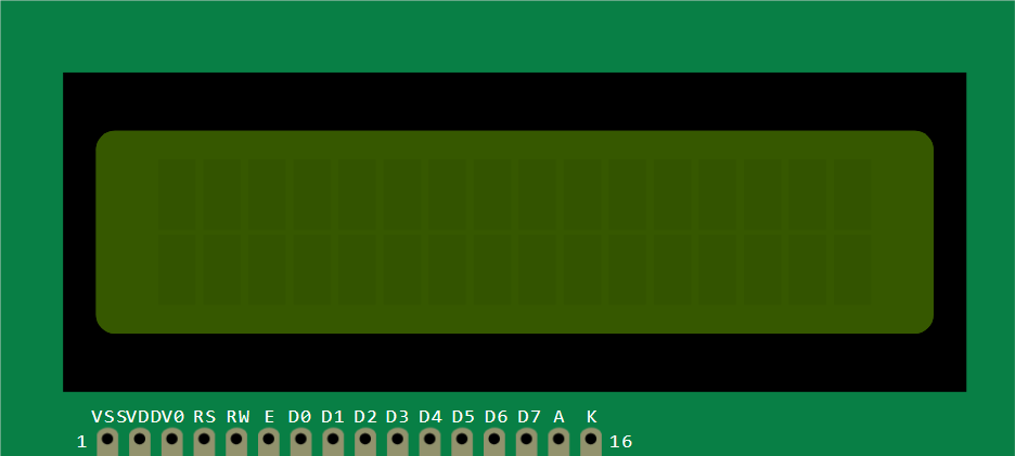
Pin Configuration and Descriptions
| Pin Number | Symbol | Function |
|---|---|---|
| 1 | VSS | Ground |
| 2 | VDD | Supply voltage for logic |
| 3 | VO | Contrast adjustment |
| 4 | RS | Register select signal |
| 5 | R/W | Read/Write signal |
| 6 | E | Enable signal |
| 7-14 | D0-D7 | Data bus lines |
| 15 | A | Anode for backlight (positive) |
| 16 | K | Cathode for backlight (negative) |
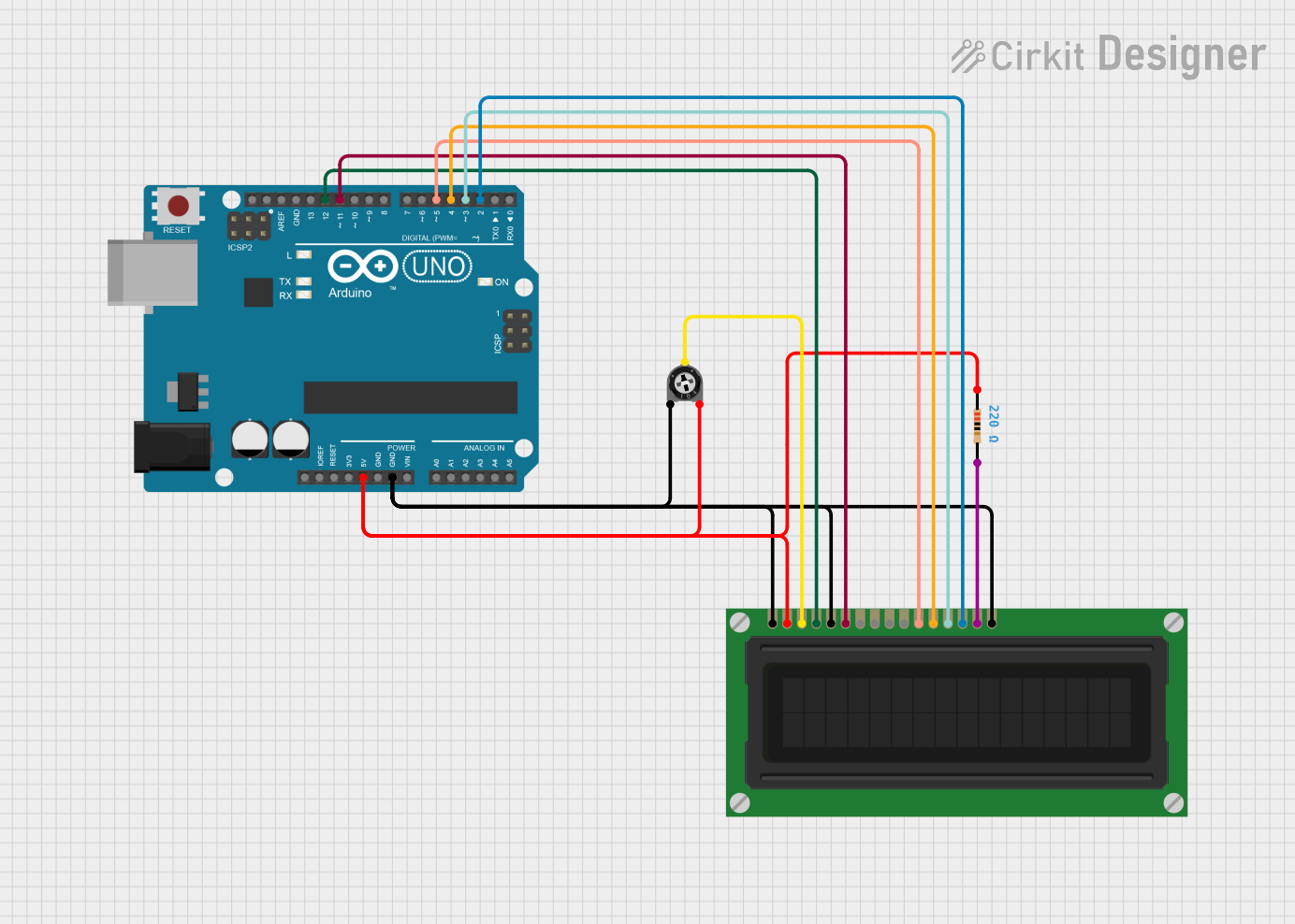
Usage Instructions
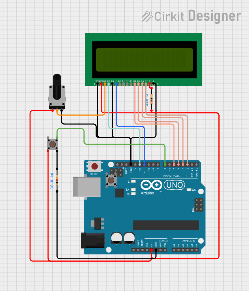
How to Use the Component in a Circuit
- Power Connections: Connect pin 1 (VSS) to ground and pin 2 (VDD) to a 5V supply.
- Contrast Adjustment: Connect pin 3 (VO) to a variable resistor or potentiometer for contrast control.
- Data Interface: Connect pins 7-14 (D0-D7) to the microcontroller data pins for 8-bit mode or use only D4-D7 for 4-bit mode.
- Control Pins: Connect RS (pin 4) to a digital pin on the microcontroller to switch between command and data modes, R/W (pin 5) to ground to set the LCD to write mode only, and E (pin 6) to another digital pin to enable data/command processing.
- Backlight: Connect pin 15 (A) to 5V and pin 16 (K) to ground to turn on the backlight.
Important Considerations and Best Practices
- Always use a current-limiting resistor with the backlight to prevent damage.
- Use a potentiometer for contrast adjustment to achieve clear visibility of characters.
- When using with an Arduino, utilize the LiquidCrystal library for easy implementation.
- Ensure that the power supply does not exceed 5.5V to avoid damaging the LCD.
Example Arduino Code
#include <LiquidCrystal.h>

// Initialize the library with the interface pins
LiquidCrystal lcd(12, 11, 5, 4, 3, 2);

void setup() {
  // Set up the LCD's number of columns and rows:
  lcd.begin(16, 2);
  // Print a message to the LCD.
  lcd.print("Hello, World!");
}

void loop() {
  // Set the cursor to column 0, line 1
  // (note: line 1 is the second row, since counting begins with 0):
  lcd.setCursor(0, 1);
  // Print the number of seconds since reset:
  lcd.print(millis() / 1000);
}
Troubleshooting and FAQs
Common Issues Users Might Face
- Display is on but not showing characters: Adjust the contrast potentiometer.
- Characters are corrupted or not displayed correctly: Check the data connections and ensure proper initialization in the code.
- Backlight not working: Verify the connections to pins 15 and 16 and the current-limiting resistor.
Solutions and Tips for Troubleshooting
- If the display is not initializing, reset the Arduino and check the wiring again.
- Ensure that the library used in the code matches the LCD module specifications.
- For issues with displaying characters, try sending a clear command to the LCD before printing new characters.
FAQs
Q: Can I use the 16x2 LCD with a 3.3V system? A: While the LCD is typically operated at 5V, some modules can work at 3.3V with reduced contrast. Check the datasheet of your specific module.
Q: How can I display custom characters? A: The LiquidCrystal library allows you to create custom characters. Refer to the library documentation for creating and displaying custom characters.
Q: What is the maximum length of the data bus wires? A: Keep the data bus wires as short as possible to prevent signal degradation. Typically, a few inches to a foot is acceptable, depending on the electromagnetic environment.